Jekyll2023-12-30T11:29:47+01:00https://there.oughta.be/feed.xmlthere.oughta.be/There oughta be a blog with awesome projects. A collection of overcomplicated devices nobody needs. A sanctum for all the things that did not get living room clearance, but oughta be seen by fellow nerds.There oughta be a 37c3 talk and music2023-12-30T00:00:00+01:002023-12-30T00:00:00+01:00https://there.oughta.be/a/37c3-and-musicJust a quick update on two things that happened recently without being a new projekt:
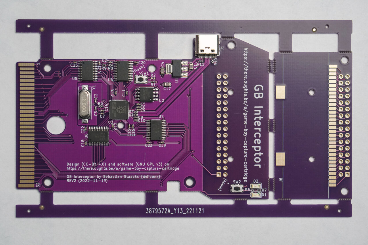
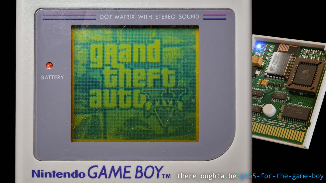
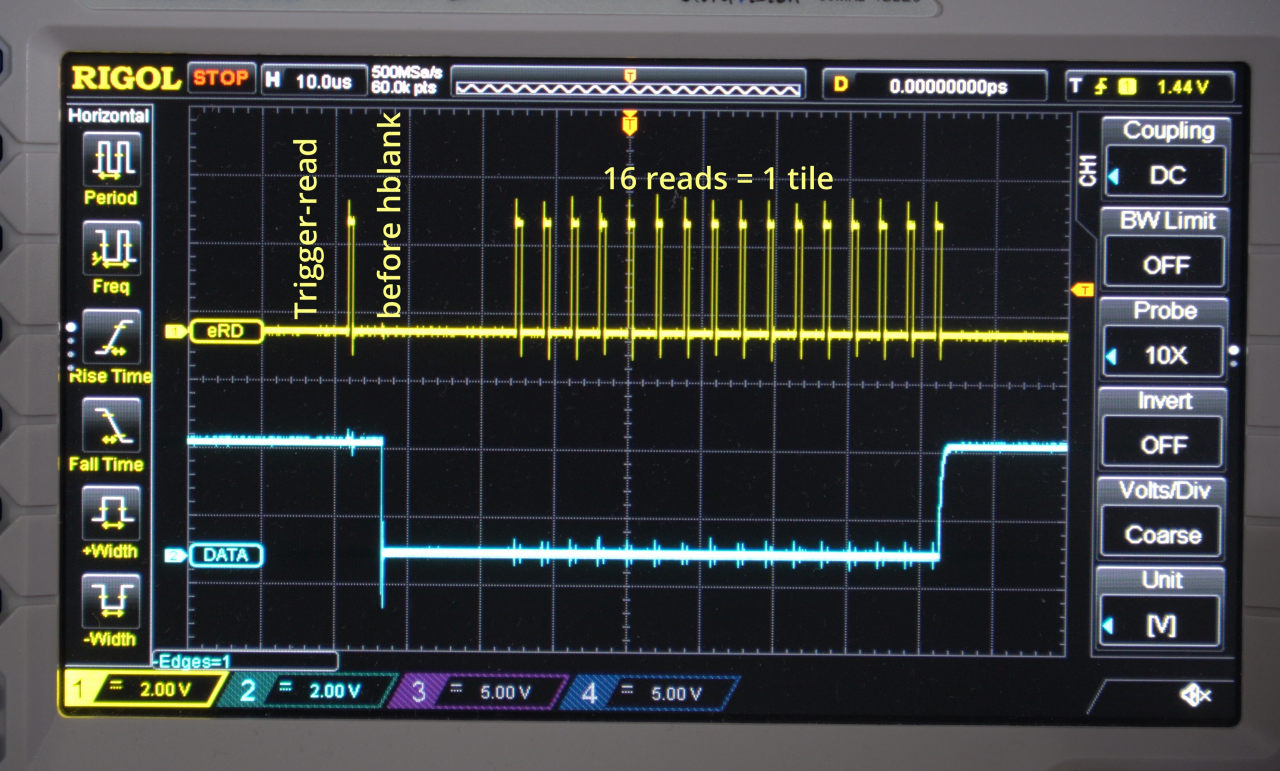
I gave a talk at the 37th Chaos Communication Congress about how the GB Interceptor can reconstruct the Game Boy’s screen content by listening in on the memory bus. The recording is available at media.ccc.de.
Click the image to see the video on media.ccc.de.
Because some asked for the music from my recent video about the wooden Game Boy (some as in a handful, I am not under the delusion that the world was waiting for my video soundtrack) I have uploaded it as a pure mp3 as well as making it available on common streaming services. You can find more details on there.oughta.be/music.
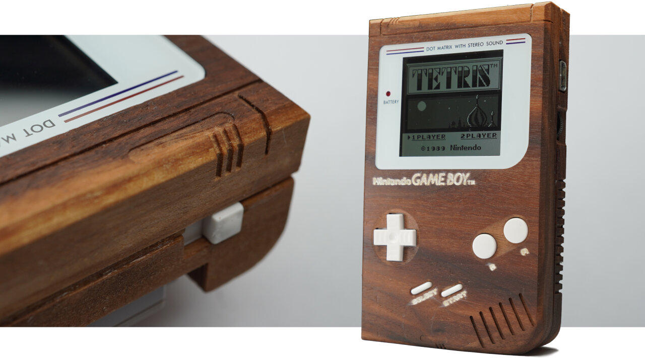
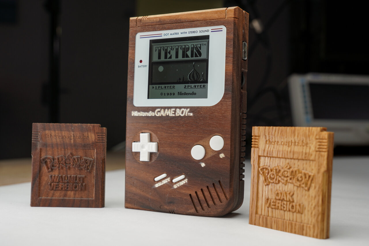
]]>There oughta be a wooden Game Boy.2023-11-03T00:00:00+01:002023-11-03T00:00:00+01:00https://there.oughta.be/a/wooden-game-boyYou made me create a wooden Game Boy shell. Yes, you made me do it. After I got myself a CNC machine a while back I just made a wooden Game Boy cartridge to get to know the machine, but social media wanted more. So, I made a Game Boy out of walnut wood.
Click the image to see the video on youtube.com.
You can see the process in the video without much explanation. If you want to learn about the toolpaths, my reasoning behind a few things, lessons learned and what you should avoid if you try this yourself, read this blog post instead and check out my design files on GitHub.
Please note that this article contains affiliate links, i.e. links that tell the target site that I sent you there and that earn me a share of their revenue in return, i.e. as an Amazon Associate I earn from qualifying purchases. In contrast to regular external links, such affiliate links are marked with a dollar sign instead of a box.
A wooden Game Boy
This project mostly began as a user request. When I got myself a CNC router a few months ago, one of the little exercises I did was a wooden Game Boy cartridge (see Youtube short clip or project files on GitHub). It was a mix of “let’s see if I can do that” and “sure the retro gamers on social media will love this”, but I did not expect how much they would love it and of course they asked for more. So, I did some testing, spent some time and several weeks later I find myself in the possession of a Game Boy with a beautiful walnut wood shell.
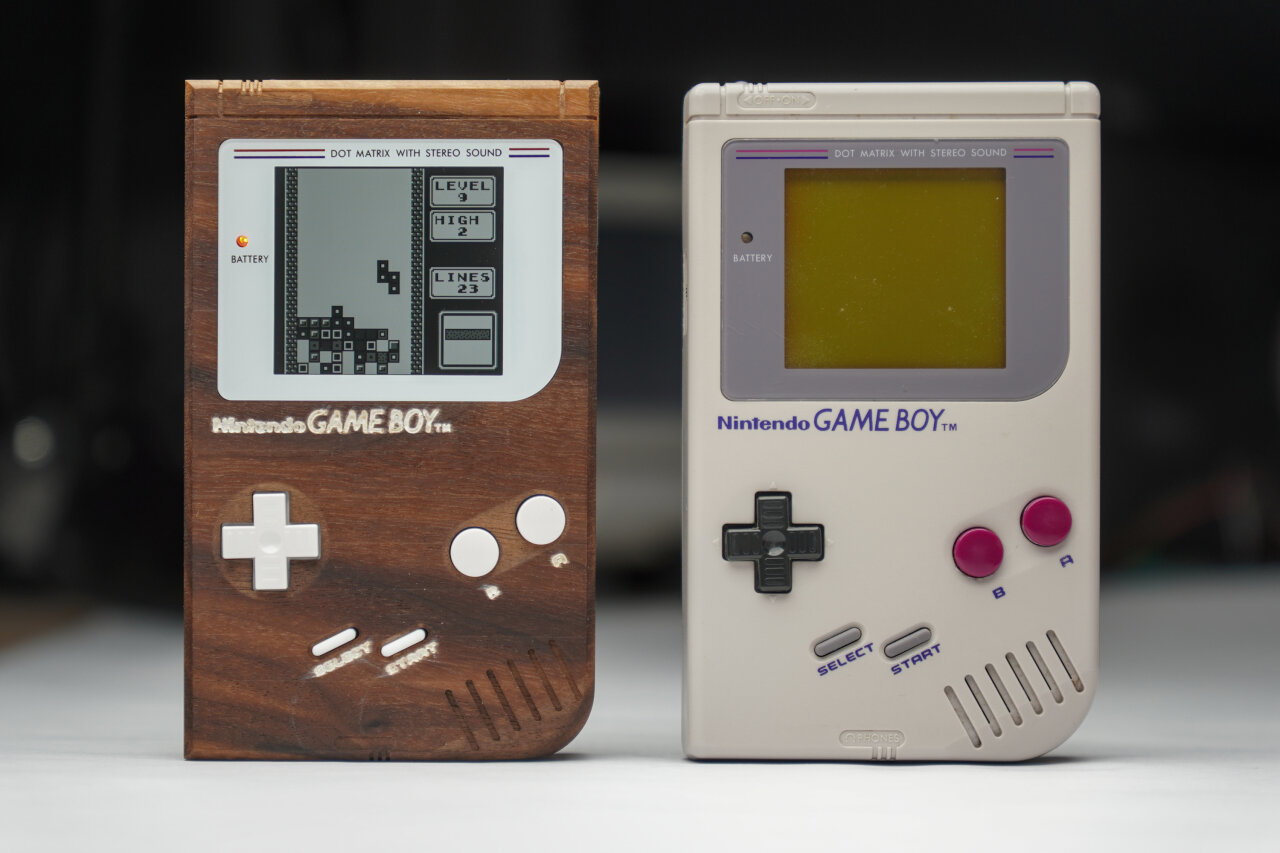
The wooden Game Boy next to its iconic ancestor.
I mean, look at that thing. Isn’t it gorgeous? So, if you want to learn how exactly it was built, read on. If you just want to see some CNC timelapses and detail shots of the wooden Game Boy, you should probably watch the Youtube video instead.
Important notes
Before we go into details, there are some general things you should know to properly judge the results. At least if you plan to reproduce the Game Boy, you should read these carefully.
I am a total noob. Yeah, I know that Game Boy does not look like the work of a noob and I would like to believe that I have proven that I can use a CNC router, but the noobness does not necessarily refer to the complexity of the project or my ability to wield some 3d software. This is more about best practices and hardware suggestions. I document what I did and which tools I used, but you should be aware that what I did mostly uses the first method I learned and the tools are the first tools of this kind that I own. They worked to create that Game Boy, but I lack the experience to tell if they are the best or even good methods/tools for this job.
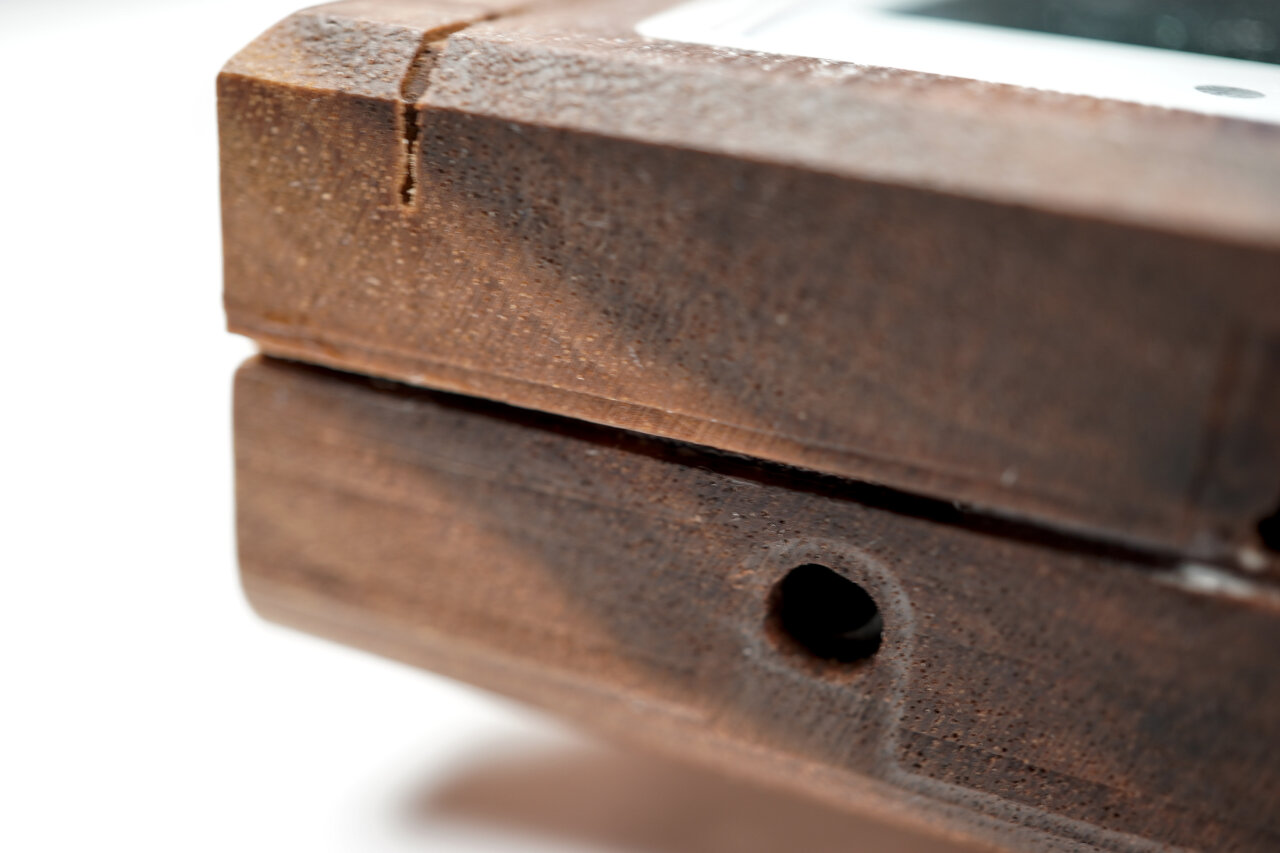
Related to this, I barely have any experience with wood. I have applied what I learned from some videos, but I have no idea how long that Game Boy will last. Wood tends to grow, shrink and bend over time, especially if exposed to changing humidity. This Game Boy could become something that I pass along to my grand children or it could crack open tomorrow. I literally have no experience to make any assumptions about this.
The project is far from perfect and many design choices were made as it went along. At the end I knew some things better than at the beginning and some later toolpaths are designed to fix problems of the earlier one. The Game Boy you see here is my successful first attempt, but this also means that the design files have not been polished or tested a second time.
I designed this Game Boy around aftermarket parts and especially for using an IPS mod. It should also fit original displays, but I have not tried that.
In the end I closed the case with wood glue, because the original screws did not hold it together properly. So, there currently is no way to open it for maintenance. Read the notes of the drilling toolpaths for more info and thoughts on the problem.
Project files and software
Let’s start with the bad news for most of those who already have a CNC machine and just want to reproduce my work: I use the Blender CAM plugin. Yes, there is a CNC CAM plugin for Blender and it is free. Yes, it is quite versatile and powerful. Yes, using it is a pain in the ass even if you are used to Blender.
Still, I love it and the CAM alternatives that seem to allow me to do similar things are very expensive1. So, I ended up using Blender CAM, which unfortunately means that many CNC users out there will cry before having to copy my models to their CAM to painstakingly recreate the toolpaths there.
Therefore, the project files are blend files on GitHub and I release everything under the Creative Commons Attribution 4.0 license. Do what ever you like with it, just make sure to mention me as the source. …and maybe keep in mind that Nintendo might want to have a word about trademarks if you try to sell these with their logo on it.
In addition to the blend files I have also uploaded the gcode files that I actually used. They are for grbl-based machines, but even if your CNC uses a grbl controller it is a bad idea to just feed them to your machine. You will have to adapt it to the equipment that you actually use and I only added them as reference to review and compare.
Speaking of equipment-specific things: The feeds and cutting depths set in the blend files are for the weak spindle on my machine. If your spindle is stronger, you can quite certainly go a lot faster. But also keep in mind that the speeds in the blend files do not have any meaning. My spindle is not digitally controlled and since it has little torque at lower speeds I pretty much used it at its maximum of 10,000 rpm. You will have to adapt this to your machine and your bits.
The hardware I used
Remember that I only got my CNC machine a few months ago, so do not expect comparative insights here. I will document what I use and try to explain a few things to people who have never used a CNC before. If you have a CNC and are just interested in the toolpaths, you can probably skip to the table with bits I used.
The CNC machine
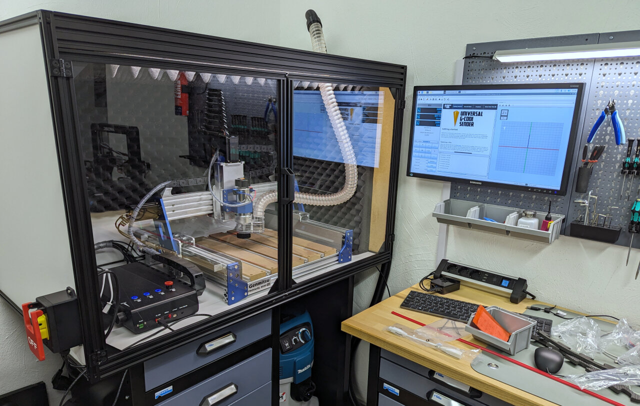
If you have never looked at CNC machines before, this probably looks like a very fancy and professional setup. If you know about CNC machines, you probably recognize immediately that it isn’t. My machine is a Genmitsu PROVerXL 4030 V2, which is the toughest Genmitsu CNC router, but in the world of hobbyist CNC machines ranks somewhere in the middle. It is much more rigid than the small 3D printer like machines (that Genmitsu machines are often associated with), but much smaller and weaker than machines by more prestigious brands.
As a beginner I think that it is extremely capable for my needs, but its weak spot is its stock 400W spindle. Compared to stronger machines you will find that my toolpaths take much longer as I am doing significantly shallower cuts. Also the spindle is pretty much limited to its top speed of 10,000rpm as it seems to lack torque at lower settings. For the finer tools I would have wished for a higher speed and for some situations a reduced speed might have been beneficial as well. Luckily, this can be upgraded and I probably will do so in the future.
In the end, I mostly chose the 4030 V2 because of its rather small footprint. While others might consider this to be a disadvantage, it was the largest machine that I could fit into an enclosure onto my workbench. Since I do not have a proper wood workshop, the machine has to share a room with other hobbies in my basement, which means that I needed to address noise and dust, because CNC machines can deliver plenty of both.
My setup looks fancier than it actually is. The enclosure and dust extraction are necessary in a regular room while the machine itself is not that large or fancy after all.
Just a few warnings if you are thinking about picking up CNC as a hobby: Do not underestimate the noise and the amount of dust such a machine produces. The enclosure and dust extraction in my case ate up a huge part of my budget for a good reason. If you are in a dirty workshop far from other people you can ignore the enclosure, but please still think about your hearing and your lungs. I highly recommend to use a dust extraction system anyway and if you are doing this in a room that you spend a lot of time in or that you use for other things in general, a simple shop vacuum will not be enough. Fine saw dust will escape regular vacuums and you should really look into ones with a filter for dust class M.
Oh, and one more warning: I do not have a problem to leave my 3D printer unattended as long as I can check in once in a while through a webcam. The typical 3D printer accidents turn the machine into a PLA spaghetti factory, but it is still ok if you stop it 15 minutes later. The more dangerous typical fail state of a 3D printer is a cable fire especially on cheap printers like mine, but if you place your printer in an environment of low flammability there is plenty of time to recognize the problem before severe consequences.
This is different for a CNC machine! If things go south with a CNC machine, they go south fast! The typical CNC accident means driving a sharp piece of metal rotating at 10,000 rpm into something that was not supposed to receive that piece of metal. You can break a lot of stuff within seconds and that is the harmless case. Imagine running that 10,000 rpm metal stick into a dry piece of wood and leaving it there because of a failure or maybe because that wood got loose and now follows your machine. Remember those adventure movies where they make fire with a rotating stick? Do this with a 400W motor covered by saw dust and maybe with a dust extraction system sucking everything into the big container with even more sawdust.
The point is that you should not leave a running CNC machine, have a fire extinguisher nearby and make sure to have an easily accessible emergency stop that actually cuts power to your machine (in case of an enclose, put something like this on the outside). Here is a video to encourage you to take this serious.
The bits
Like in the previous section, I will be talking to people new to CNC routers here. Someone who already knows this stuff will probably just have a glimpse at the table below anyway.
While CNC machining often looks like you are just pushing a common drill bit to some wood, this is not what is happening at all (unless maybe you are actually drilling holes with your CNC). What looks like a drill bit usually is a milling bit (a so-called end mill). It is not designed to plunge vertically into the material (although in many cases it has to be able to do this, too), but to carve away material horizontally.
One interesting aspect of this is that the spiral of the bit might go in different directions. Some bits have a right-handed spiral like a drilling bit, but others can be left-handed or not even have a spiral form at all. The reason is that the actual milling is done at the side and just requires sharp edges while the spiral mostly helps to move the material away from the cutting edge. Right-handed drills are common as you want to push material upwards out of the drilling hole and for the same reason you will find many end mills with that shape. They pull material upwards and away from your work piece, therefore they are called “upcut” bits. The downside of this is that the upwards motion can fray the edges of your work piece, which is why I also often use the counterpart with a left-handed spiral, the “downcut” bit. There are also some other forms and compromises, but I only have those two variants and so for each task I have to pick a suitable diameter for my end mill (obviously you need small ones for details and large one to remove much material fast) and decide between upcut and downcut as a trade-off between a nice finish and efficient material removal especially in tight spots.
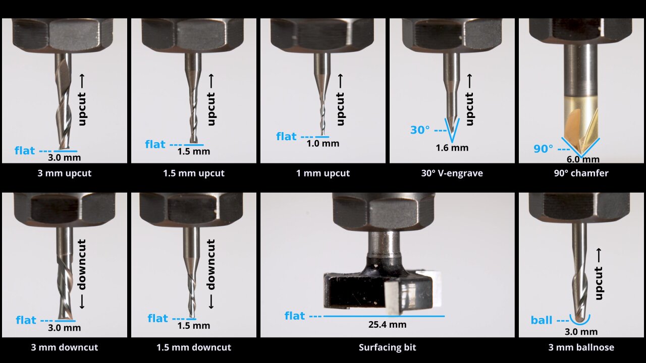
The nine bits I used in this project, roughly grouped by shape and size.
Another aspect is the shape of the tip of the bit. The most common one is the flat end mill, which is best suited to create a flat surface. However, if you want to create a curved 3D shape, this is not a good choice as it tends to create little steps that look similar to the layers of 3D printers. A ballnose bit with a circular tip can help as it can create a slope between one line to the next one.
A very important shape is the V-shape. On one hand, this is used to directly create angled edges (chamfers) in a single pass, but also they can be used to carve text or other designs. Imagine to just try and cut a small square. If you use a flat end mill with a 3mm diameter, you can quickly remove the material from the square, but the corners will always be rounded with a radius of 1.5mm. So, instead you use a smaller end mill, let’s say 1mm. Now it takes ages to remove the material2 and still have round corners, now with a radius of 0.5mm (which might be ok for many use cases). That’s where the V-bit shines: If you do not care about how deep you cut, but just want to have a 2D shape at the surface, a V-shaped bit can simply use different depths to have different diameters at the surface. Need a tiny bit for a sharp corner? Only use the very tip of the bit. Need a large diameter to clear most of that example square? Go deep for a large radius. The result is a typical angled V-carving look that many (including me) find quite pleasing. Just search for V-carving on Youtube to find a bunch of very satisfying videos.
Unfortunately, that still is not all that needs to be considered when picking the right tool for each detail. You also need to consider the cutting length and the overall clearance of your bits. The cutting length is how deep the bit can go so that its sharp bits are still cutting away material instead of its dull bits just rubbing the wood and heating it up. That’s not much of an issue for me as my weak spindle usually limits the depth of my cuts anyway. The clearance is a much bigger issue because overlooking it usually causes some kind of damage. Whenever you cut into the material (or when you use clamps to hold your stock3) you need to have enough space for your machine and the rest of the bit. The machine itself mostly becomes a problem for deep pockets, but those small diameter end mills often still have a larger shaft. So, even if you observe the cutting length, you cannot cut at the side of a straight wall if you would run the shaft of your bit into it.
That should be enough of an overview. I am mostly writing down what I learned from others (mostly Youtube) over a few months, so I would recommend that, too, if you want to go deeper.
Now, finally, here is the list of bits I used in this project and the short name I use for them henceforth4.
Please keep in mind that I only got my first CNC router a few months ago, so these are mostly the first bits I ever used. I have no comparison to tell if they are good or bad, so take this as pure documentation and not as an endorsement.
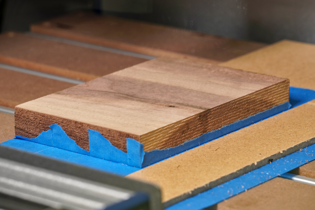
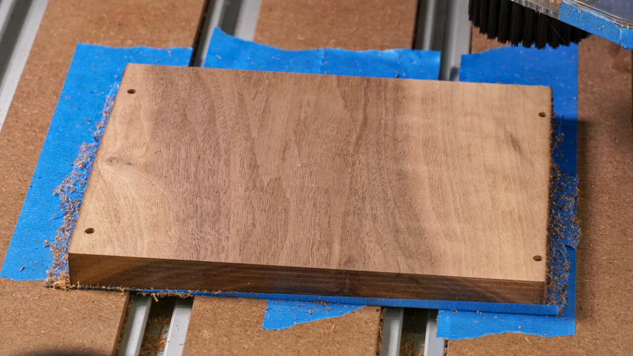
The outside of the bottom shell (A)
Ok, it’s time to get serious. In the following I will go through all the toolpaths one by one and try to remember details that you should know about. For each one I will mention the bit I used, how long it took and the name of the gcode file I used (if available). As mentioned above it is unlikely that you can use the gcode file directly, but you should be able to view it in order to understand what the toolpath does.
The first step is to create the outside of the bottom half of the shell. For this you need a piece of wood with at least 160mm by 99.6mm and it should have a thickness of at least 23mm. Having a few more millimeters is highly recommended to allow for a few surfacing steps without becoming too thin.
A01
Purpose
Tool
Gcode
Duration
Surfacing
Surfacing bit
N/A
17 min
And surfacing is exactly what we start with. The current surface will be the one visible on the back of the Game Boy shell. So, it should look nice and needs to be surfaced down to a clean even plane. Keep in mind that the remaining thickness needs to be at least 23mm even after possibly surfacing the other side too. The exact thickness does not matter yet, so just aim for a nice finish on this side.
A02
Purpose
Tool
Gcode
Duration
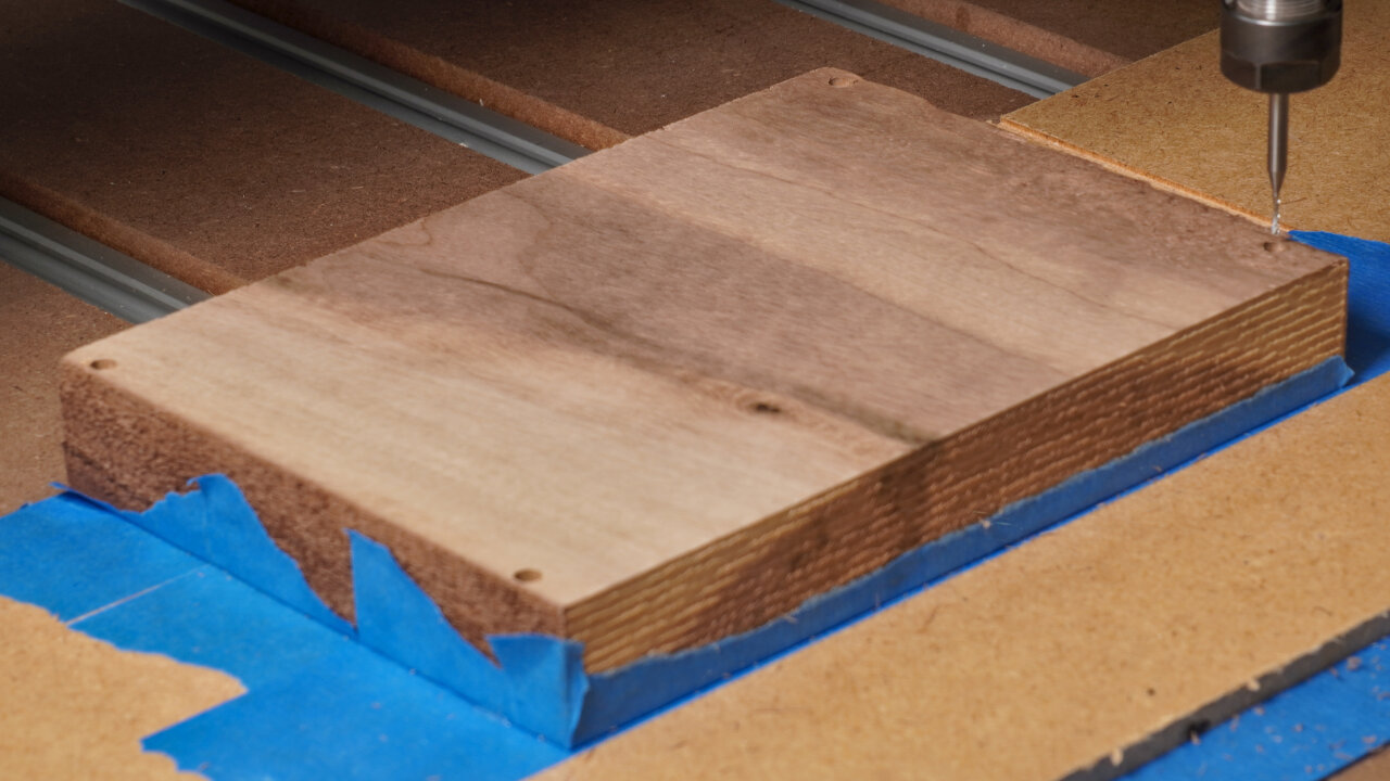
Hole to allow deep dive of 1mm bit
3mm upcut
1-reference-frame-pockets-3mm-flat-UPCUT.gcode
5 min
Reference for flipping
1mm upcut
2-reference-frame-drill-1mm-flat-UPCUT.gcode
4 min
This is my method of aligning the workpiece after flipping it. I drill small holes through to the backside that I can use to align it after turning it around. If you have a better way of doing this like a flip jig, a tool to measure distances along all three axes or even an additional axis, you can skip this toolpath.
I labeled this as a single path, but please notice that I have split it into two gcode files. The reason is that the working distance of my smallest bit is too short to go all the way through 23mm without hitting the wood with its wider 3mm shaft. So, there is a first step of drilling space for that shaft before creating the smaller and more precise holes on the backside.
If you use my solution, take note that zero is set to the corner of the Game Boy, so the hole in that corner will be drilled 5mm along negative x and y. So, when picking the start point to fit the 160mm by 99.6mm of the reference frame, keep in mind to offset zero by 5mm in both directions. This will be the zero for all subsequent steps, too.
Oh, and obviously, this step will drill through the entire workpiece and into your spoilboard.
A03
Purpose
Tool
Gcode
Duration
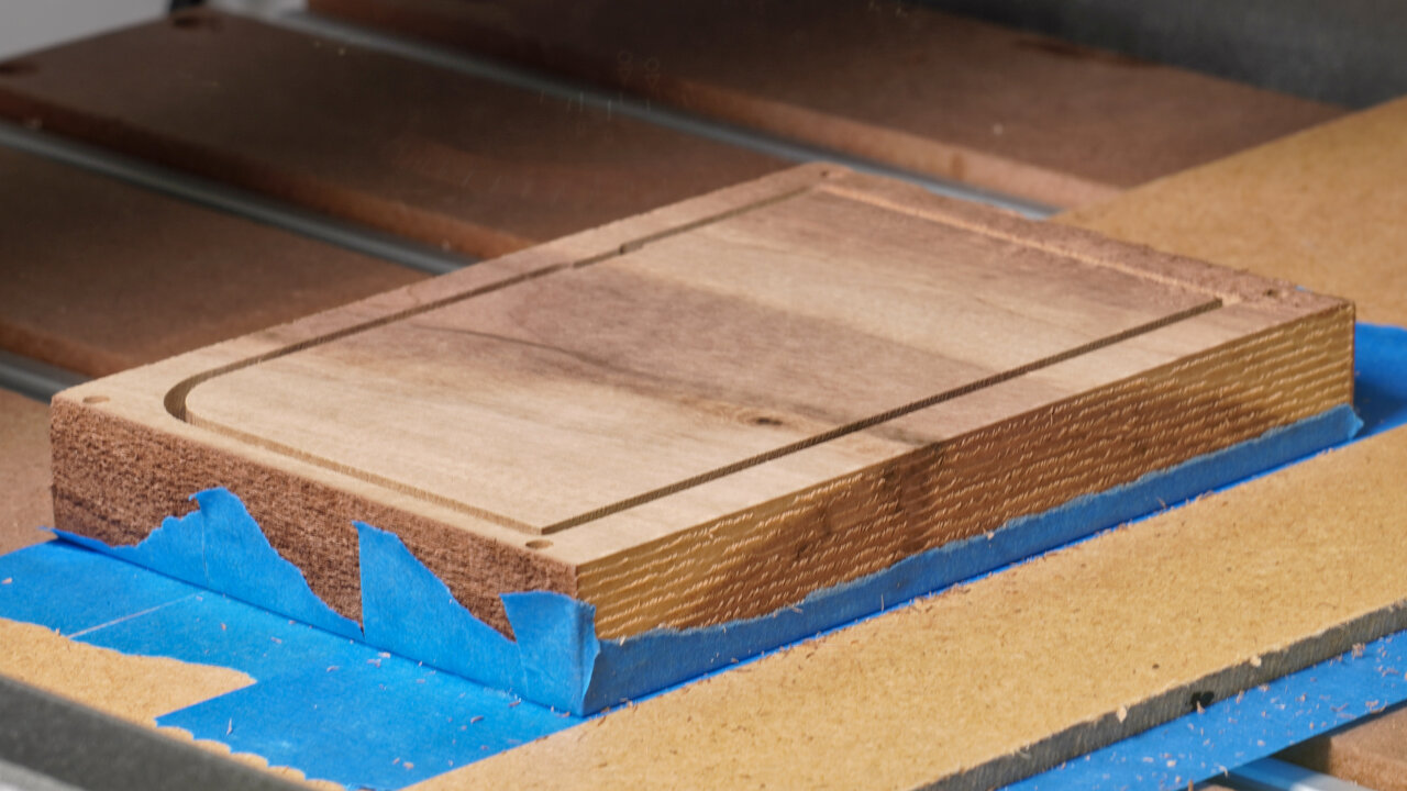
Profile cut
3mm downcut
001-bottom-outside-1-profile-3.0mm-flat.gcode
15 min
Next I do a profile cut that does not go all the way through. It will eventually meet with a profile cut from the other side (if aligned properly). At this point it also gives room for a few upcoming toolpaths that enter and leave the outer rim of the Game Boy shell.
A04
Purpose
Tool
Gcode
Duration
Curved sides of the back
3mm ballnose
001-bottom-outside-2-3d-3mm-ball.gcode
63 min
The curved sides on the back are created with a ballnose bit. However, I can still see distinct lines from the tool passes, so if you want to avoid that you need to set a higher overlap between passes or you need to do a better sanding5 job than me.
A05
Purpose
Tool
Gcode
Duration
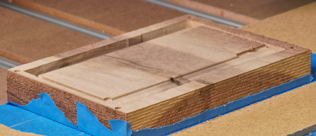
Pocketing of cartridge slot and battery compartment
3mm downcut
001-bottom-outside-3-pocket-3mm-flat.gcode
84 min
This step carves the pockets for the cartridge slot and the battery compartment. Note, that it removes more material in the battery compartment than on the actual original Game Boy shell to make space for the upcoming toolpath using a 1.5mm downcut bit. My 1.5mm bit only has about 8mm of clearance before sloping into a 3mm shaft, so in order to create the finer details inside the battery compartment some room needs to be made. If you have a bit without such a limitation, you might want to optimize this towards the original.
A06
Purpose
Tool
Gcode
Duration
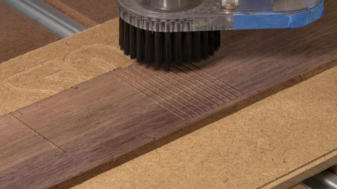
Details of battery compartment and lines on backside
1.5mm downcut
001-bottom-outside-4-details-1.5mm-downcut.gcode
40 min
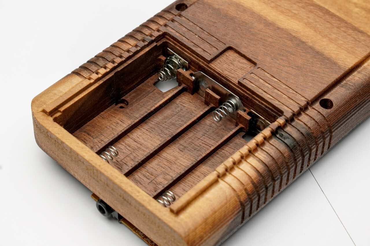
As mentioned before, this adds some details in the battery compartment. Important ones: These are the slits that will hold the battery contacts. My design is made for some after market contacts (see assembly section), but it has too much room and I needed to put something behind the contacts to hold them in place. If you know the exact contacts you want to use, this is something that could be optimized.
Oh, and this path also creates the decorative lines on the back of the Game Boy.
A07
Purpose
Tool
Gcode
Duration
Drilling screw holes
1.5mm upcut
001-bottom-outside-5-holes-1.5mm-upcut.gcode
3 min
The last step on this side drills some holes for the screws. These are not the holes the screws tap into, but the holes that the screws go through first. I have not tested the diameter much because I ended up gluing the shell, but they seemed ok.
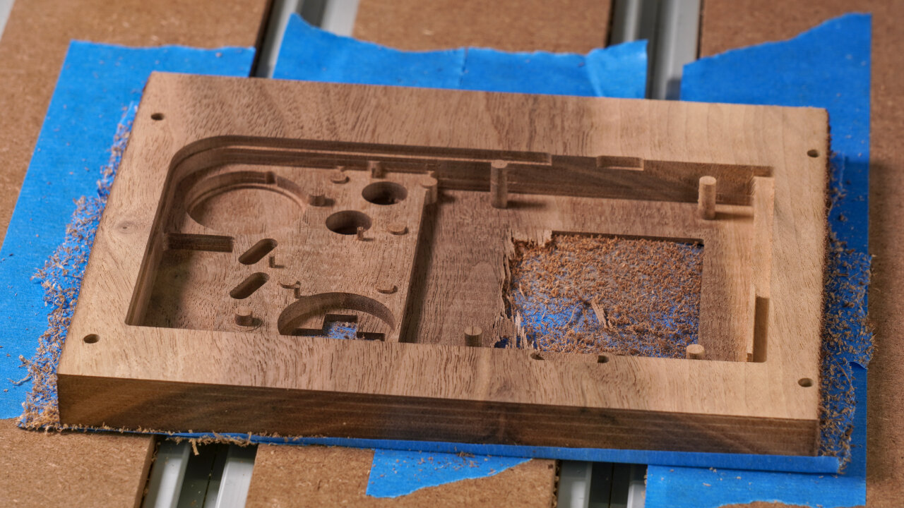
The inside of the bottom shell (B)
Now it is time to flip the workpiece to do the inside of the bottom half. To do so, align it with your favorite method.
If you use my reference drills, align your workpiece such that you can jog 160mm along x and 99.6mm along y and always end up on one of the small 1mm holes as precisely as possible. Remember that you cannot fix the rotation of your workpiece if you use the tape and glue method (like I do), in which case I would recommend using a carpenter’s square to get the orientation right while gluing it and then use the holes to verify and to set zero.
Speaking of zero on my reference frame: Remember that the hole is at -5mm and -5mm, so align your bit above the correct hole and then move it by 5mm along x and y before setting zero. Keep that zero for the rest of the steps for the bottom half.
B01
Purpose
Tool
Gcode
Duration
Surfacing
Surfacing bit
N/A
depends on original thickness
Once again, it is time for surfacing. However, this time you are aiming for a final thickness of exactly 23mm. Of course, if you need to remove a lot of material, you can use a different method first, but at the end of this step you should have a perfectly flat workpiece with a thickness of 23mm. I designed the two sides to allow for a little uncertainty here, but I would say that you should hit 23mm to within about half a millimeter.
B02
Purpose
Tool
Gcode
Duration
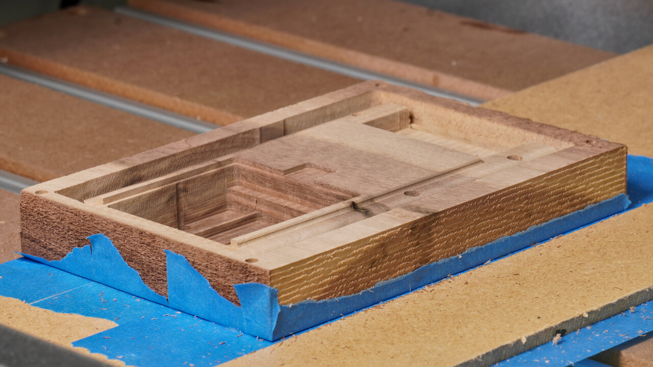
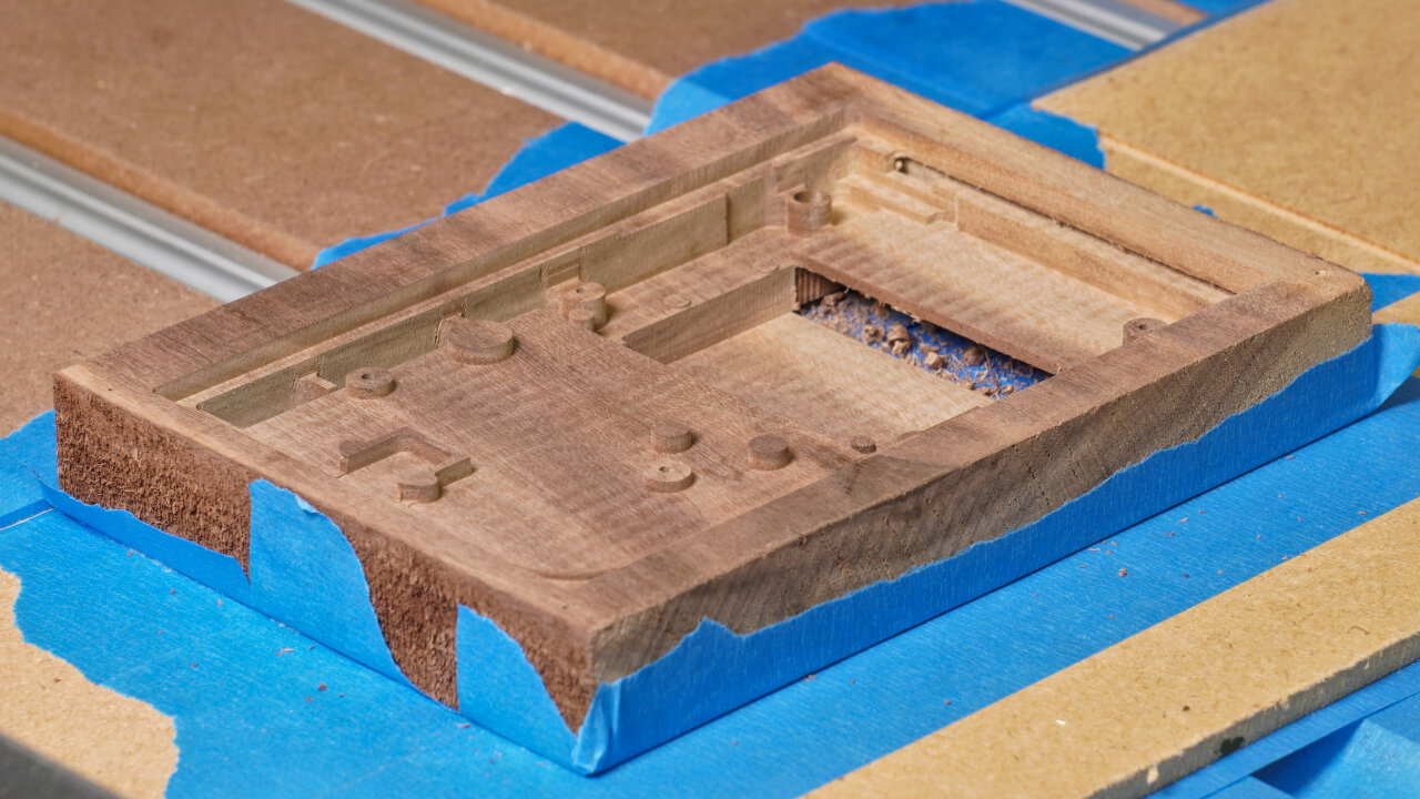
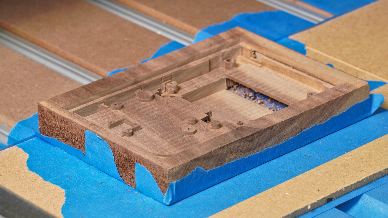
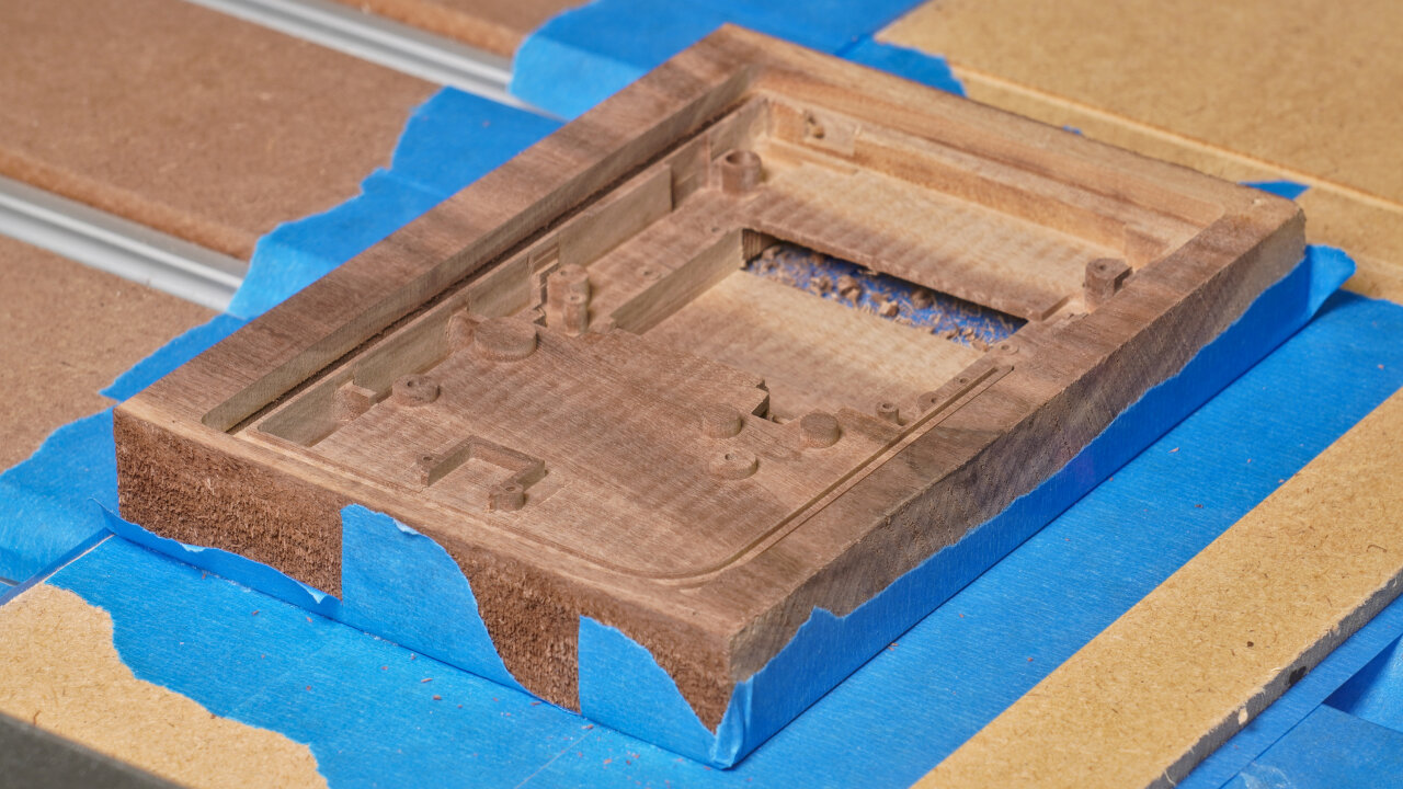
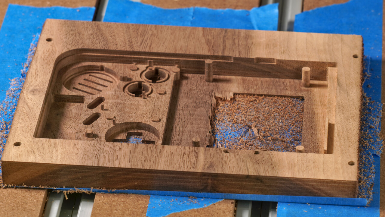
Pocketing of most internal geometry
3mm downcut
002-bottom-inside-1-pocket.gcode
211 min
This is the big workhorse step for this side. This removes most material to make room for the PCBs and it creates most of the relevant geometry inside. However, my gcode had a few problems here that you might want to improve on:
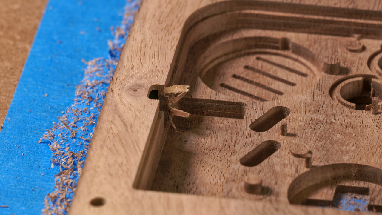
I manually created layers for the pocketing that are far from optimal. By now I know better methods to do this, but at that time this was the best I could do in Blender CAM. The current toolpaths are inefficient and imprecise in a few places. You might want to recreate them with your preferred software (and especially if you have a beefier machine that can handle deeper cuts).
A big mistake here is that one or two of the lower toolpaths accidentally cut away the lip and part of the rim of the shell near the power switch as well as the screw post near that switch. I compensated for that with a larger lip on the top half of the shell, but that is far from perfect. The reason for this error seems to be a boolean operator that did not work properly and failed to subtract that part of the rim from the pocketing area. Whatever the reason, you should carefully look at what would happen to the rim at the top of your Game Boy.
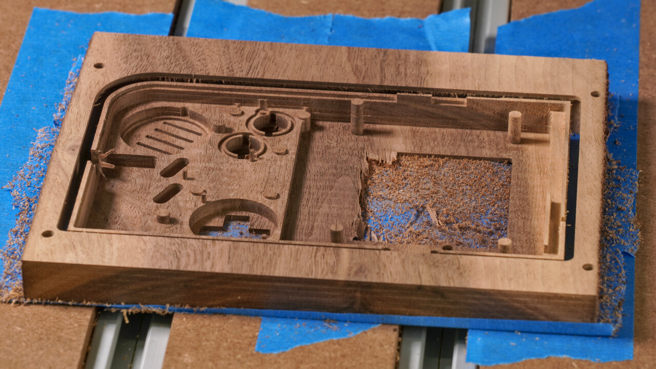
Some parts were a bit imprecise. The screw posts for the metal shield of the Game Boy come to mind or the lower end of the link cable cutout. If you want to be precise, check out my photos and adjust things that are not perfect.
B03
Purpose
Tool
Gcode
Duration
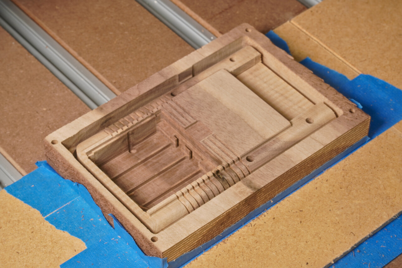
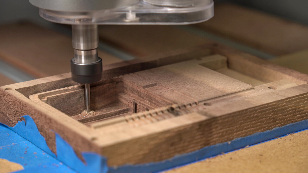
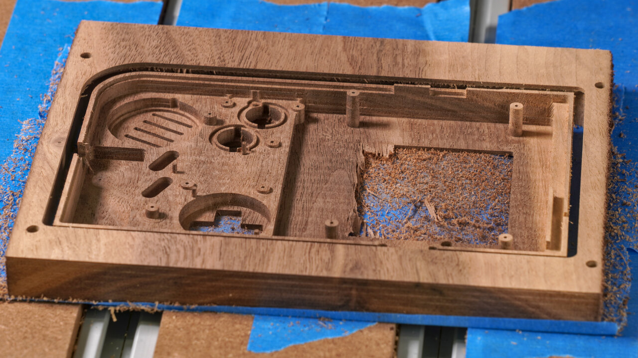
Finer details of internal geometry
1.5mm upcut
002-bottom-inside-2-fine-1.5mm-upcut.gcode
48 min
First of all note that as far as I remember, the only reason for using an upcut bit here is that my 1.5mm upcut is a few millimeters longer than my 1.5mm downcut. If this is not a limitation for your tool, you should be fine with a downcut end mill, too, except maybe for some drilling for the screws.
This step adds some details to the power switch part, the battery contact cutouts for the main PCB and some small details like a little cutaway behind one of the screw posts to make space for the speaker cable. It also drills holes for the screws to tap in. In my experience the 1.5mm holes do not hold the thin original screws reliably. On the top half I will later drill 1mm holes, which unfortunately tended to break if a screw is tapped into a pole. So, some experimentation with alternative screws and drilling diameters might be in order here, especially if you plan to use a different kind of wood.
B04
Purpose
Tool
Gcode
Duration
Profile cut
3mm downcut
002-bottom-inside-3-profile-3mm-downcut.gcode
11 min
And here is the final profile cut that should meet the profile cut you did on the other side. Note that I use the tape and glue method and did not have to consider any clamps. If you use something else you have to think about bridges if required.
This is where you find out if you have aligned your workpiece properly.
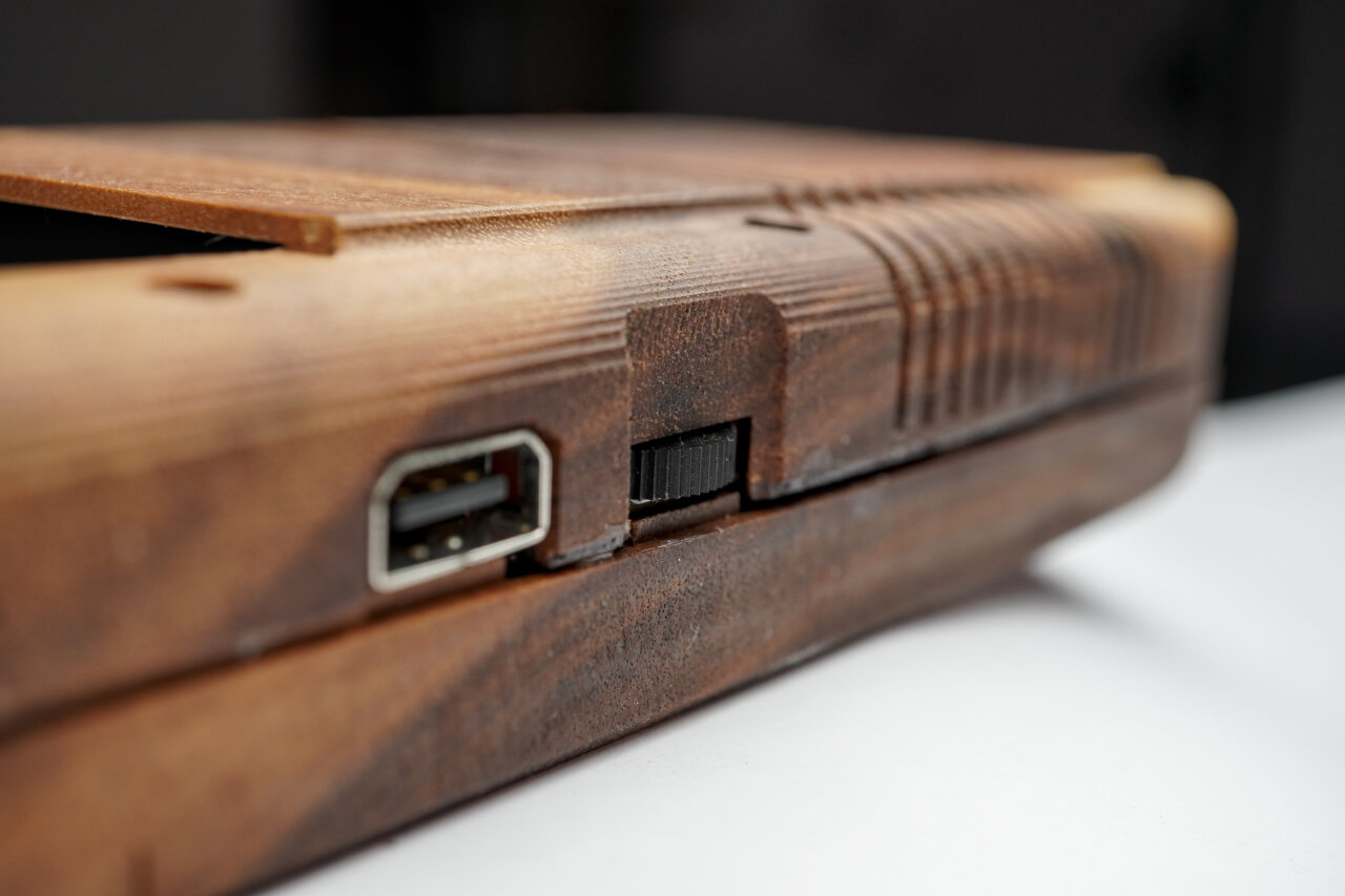
The hole for the AC adapter needs to be made by hand.
A little detail you should note here is that I did not figure out a reasonable way to create the hole for the AC adapter plug. I ended up manually creating it with a file after the bottom shell was complete.
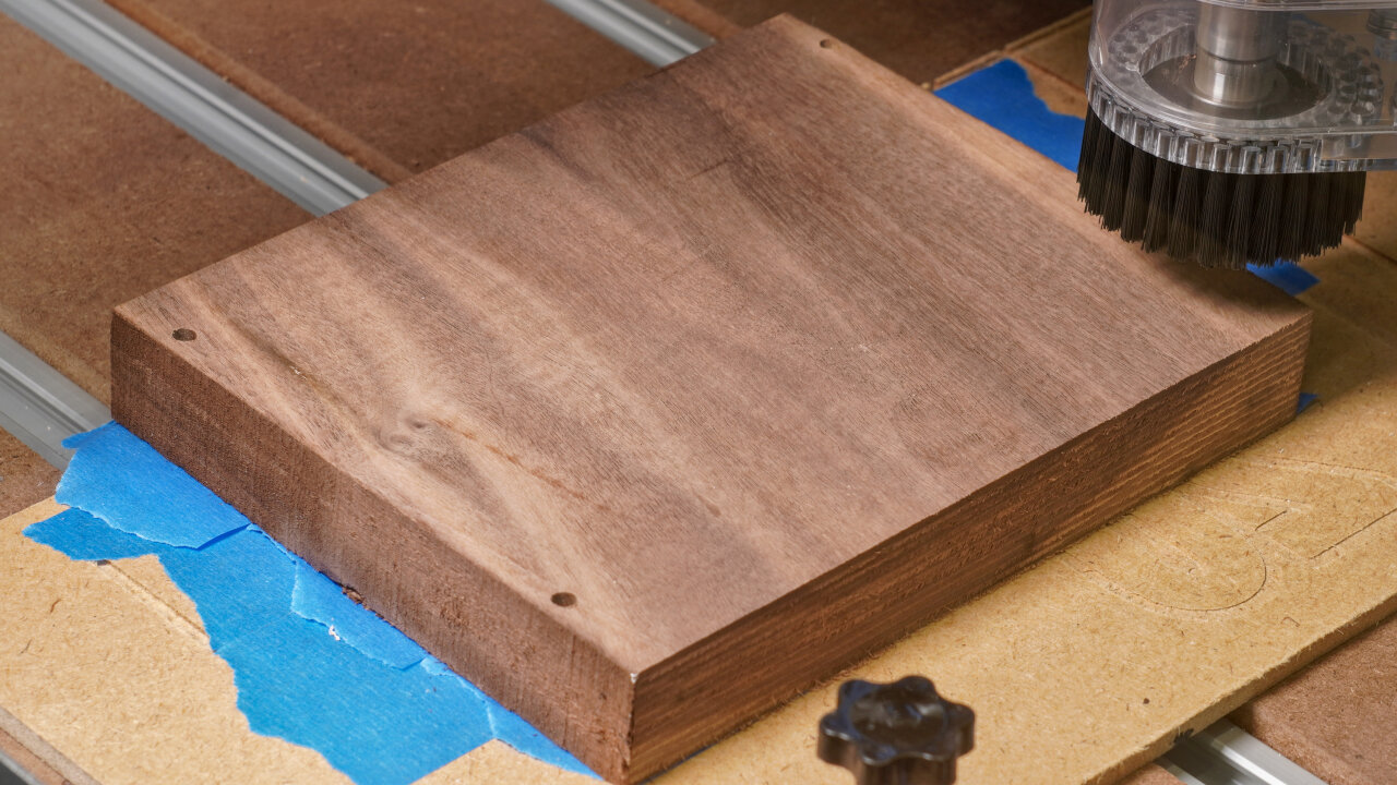
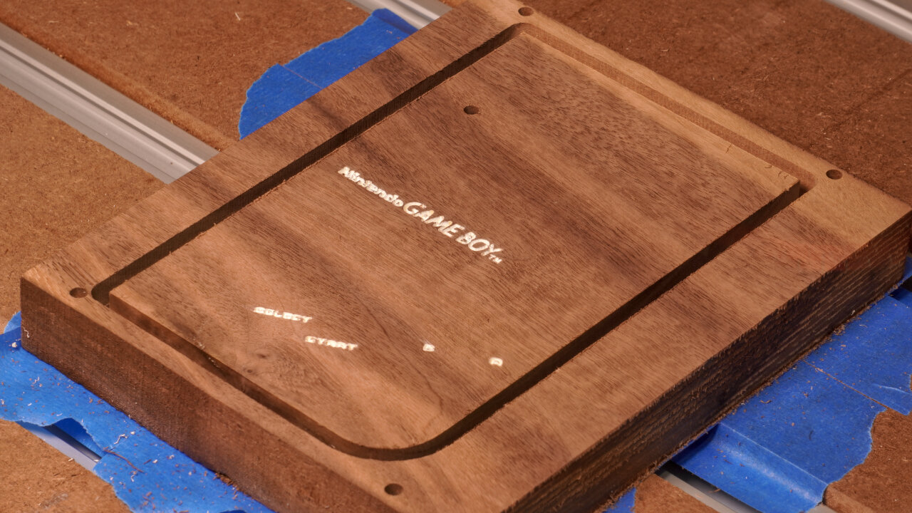
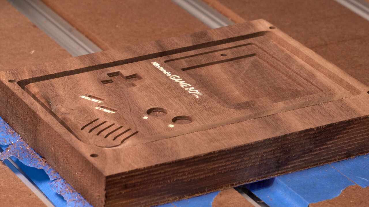
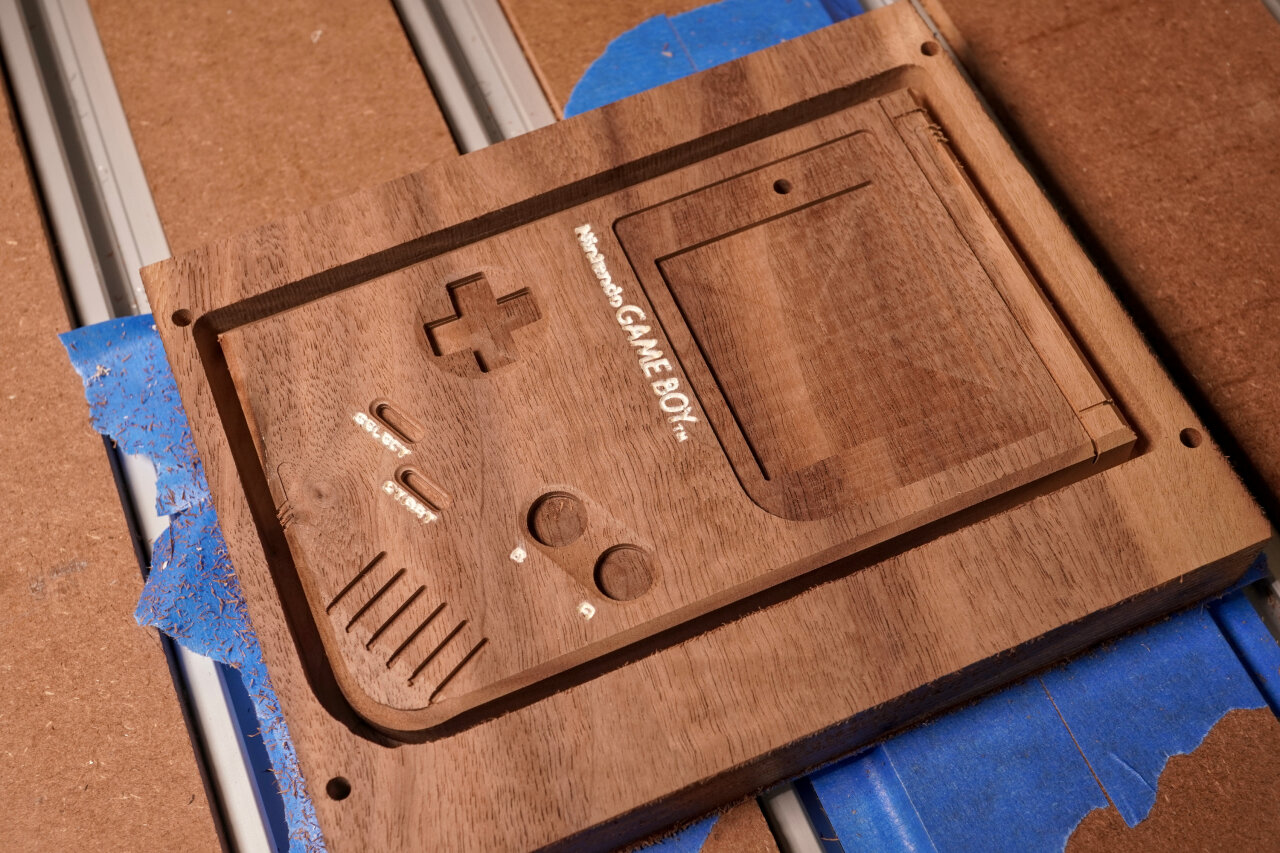
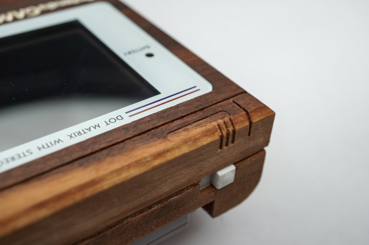
The outside of the top shell (C)
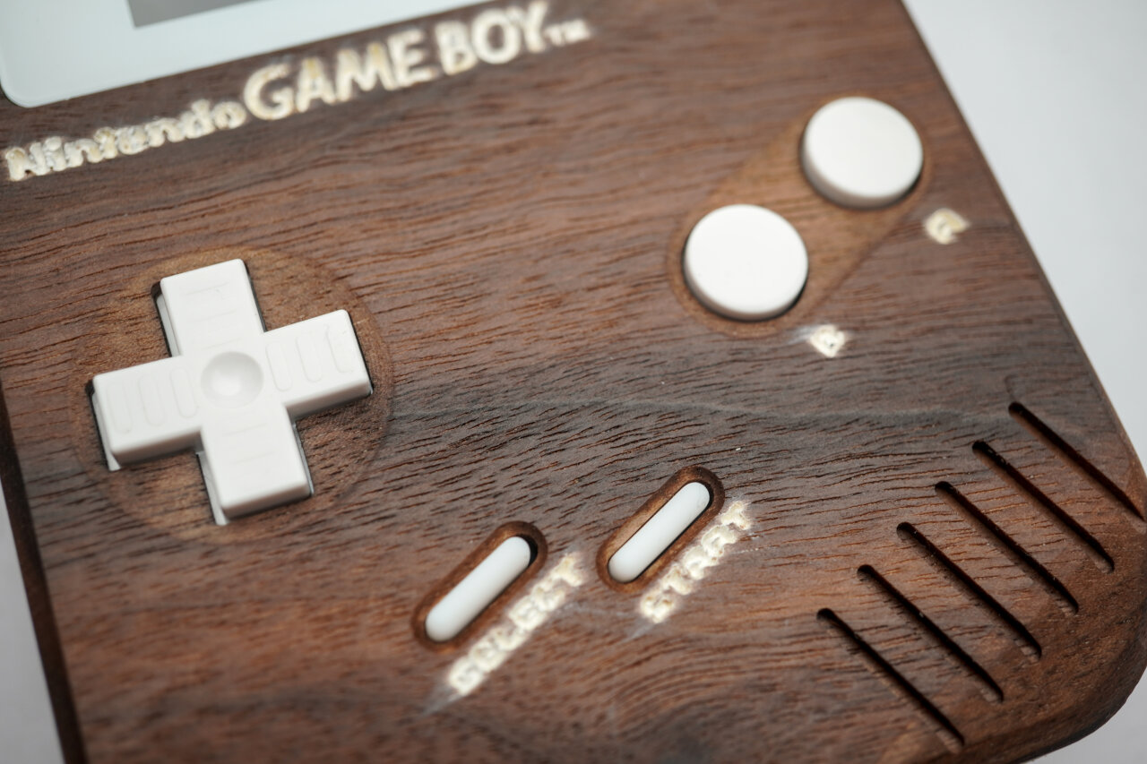
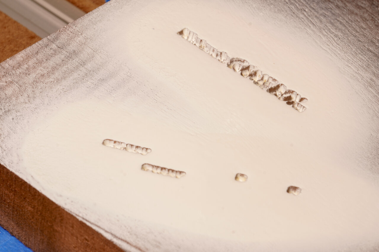
Now it is time for the iconic front of the Game Boy. Please read steps C02 to C03 carefully and think about them. These are the common sign-maker’s method of doing a V-carve, painting everything and then cutting away the excessive paint. I have little experience here and this is the part of my wooden Game Boy that I am absolutely not happy with. My method (or choice of paint or choice of tools or whatever) lead to quite some smearing of the paint and letters that look soft and unfocused.
The white paint looks soft and some circular smearing from the surfacing bit is visible.
If making the entire wooden Game Boy was less time intensive, I would probably have another try with white epoxy instead of paint. I also notice that many hobby CNCists6 use a belt or disc sander for this instead of a surfacing bit, so maybe that’s part of the problem. If you recognize why this did not work out so nicely in my case, please let me know. Anyhow, below is what I did to get the Nintendo logo and labels onto my Game Boy and you might want to think about a different method.
You will also notice that I did not list a surfacing step. That’s because my method involves V-carving below zero and a later surfacing step anyway. Depending on what you want to do, you might want to surface first.
C01
Purpose
Tool
Gcode
Duration
Hole to allow deep dive of 1mm bit
3mm upcut
1-reference-frame-pockets-3mm-flat-UPCUT.gcode
5 min
Reference for flipping
1mm upcut
2-reference-frame-drill-1mm-flat-UPCUT.gcode
4 min
Again, the reference for flipping. Again, skip if you prefer a different method. And again, if you use mine, remember to offset zero by 5mm along x and y.
But there is one important difference: If you use my method of painting you will have to remove the workpiece, paint it, replace it and realign it on the same side. That might not work with a flip jig if it cannot be fixed to your machine’s bed.
C02
Purpose
Tool
Gcode
Duration
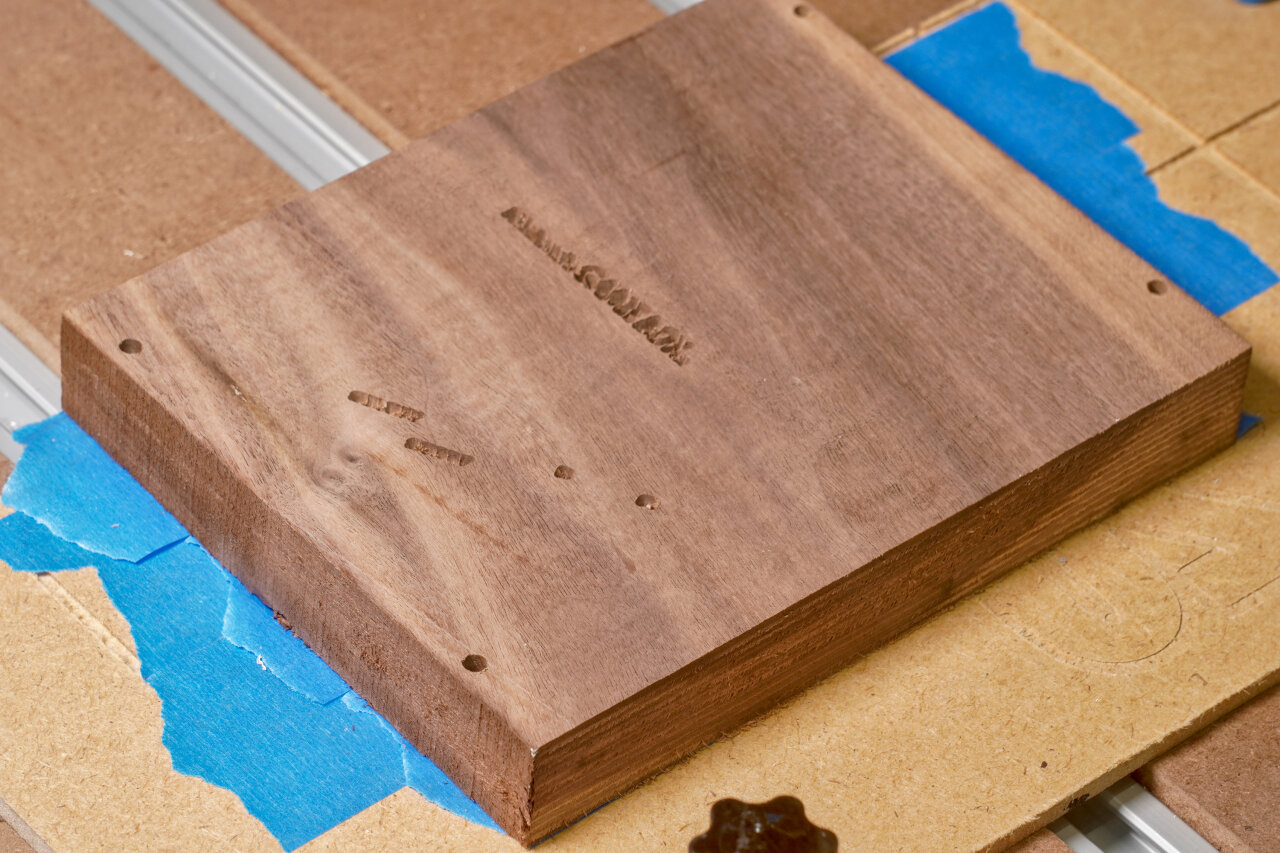
Engraving Nintento logo and button labels
30° V-carving
003-top-outside-1-label-30deg-v-carve.gcode
16 min
Now, this engraves the Nintendo logo and button labels with a V-shaped bit. I actually ran that toolpath twice: Once starting from the surface (resulting in perfect letters at the surface) and then again starting 2mm below the surface. This is because I will later remove 2mm to return to the perfect letters and remove excessive paint. I did this in two steps because I was not sure if plunging a total of 4mm directly would be too much (now I think it wouldn’t). Also, 2mm might be a bit much, but I had made the observation in earlier tests that white paint enters the wood grain even with a clear coat primer, so I wanted to be safe.
Painting
A step that is not a toolpath. Paint your workpiece such that the logo and labels are properly colored. I used spray paint for this and first applied several layers of clear coat as a primer. After it had dried completely, I added several layers of white spray paint. The point of the primer is mostly to prevent white paint from entering the wood grain and showing up several millimeters deeper where it should not be visible. Make sure to seal up every part that could get sprayed with white paint - not only the actual letters.
Any suggestions on improving this method are welcome.
And of course, I had to remove my workpiece for this step. If you apply paint with a brush, you might be able to do this in place.
C03
Purpose
Tool
Gcode
Duration
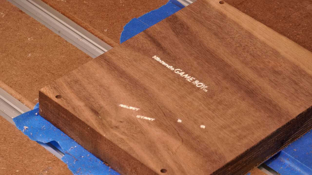
Surfacing
Surfacing bit
N/A
25 min
Here I now removed the 2mm that I dove too deep during V-engraving. This removes all the paint outside the carved area, theoretically leaving me with perfect and precise letters. However, as mentioned above I am not entirely happy with the result and you might want to consider alternative methods.
C04
Purpose
Tool
Gcode
Duration
Profile cut
3mm upcut
003-top-outside-2-profile-3mm-upcut.gcode
24 min
Next I did a profile cut and again not all the way through. This gives some room for some of the upcoming toolpaths at the edge. Also note that I will chamfer the outline of the Game Boy front, so there is no need for a downcut bit here.
C05
Purpose
Tool
Gcode
Duration
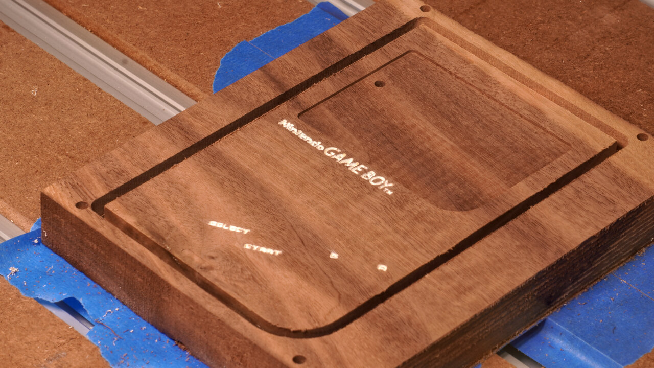
Screen bezel and LED hole
3mm downcut
003-top-outside-3-pockets-3mm-downcut.gcode
10 min
This is a simple shallow pocket for the screen bezel and a little drilling to create the hole for the power LED.
C06
Purpose
Tool
Gcode
Duration
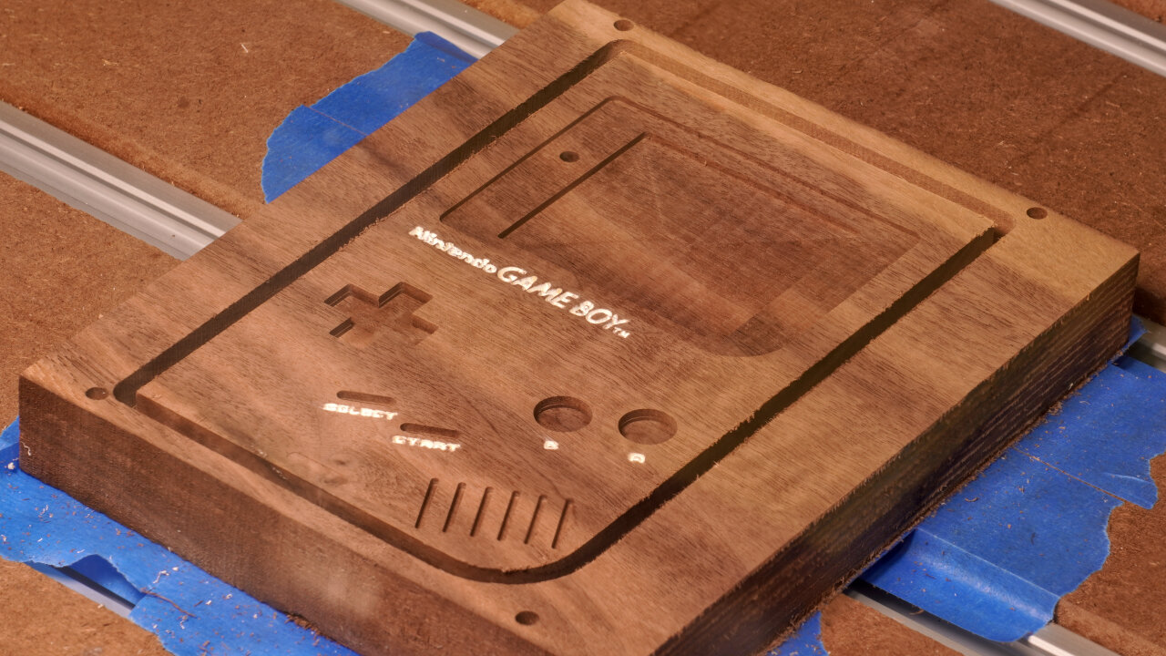
Pockets for buttons, screen and speaker grill
1.5mm downcut
003-top-outside-4-pockets-1.5mm-downcut.gcode
34 min
The pocketing of the buttons, the actual screen and the speaker grill is done with a finer bit. In some cases because of thin lines and in some cases to achieve sharper corners. In some cases because it seemed like the buttons should be part of this package.
C07
Purpose
Tool
Gcode
Duration
Rounded speaker corner and button indents
3mm ballnose
003-top-outside-5-indents-3mm-ball.gcode
21 min
The Game Boy features a slope at the speaker corner and some smooth indentations around the buttons. These are done with a ballnose bit.
C08
Purpose
Tool
Gcode
Duration
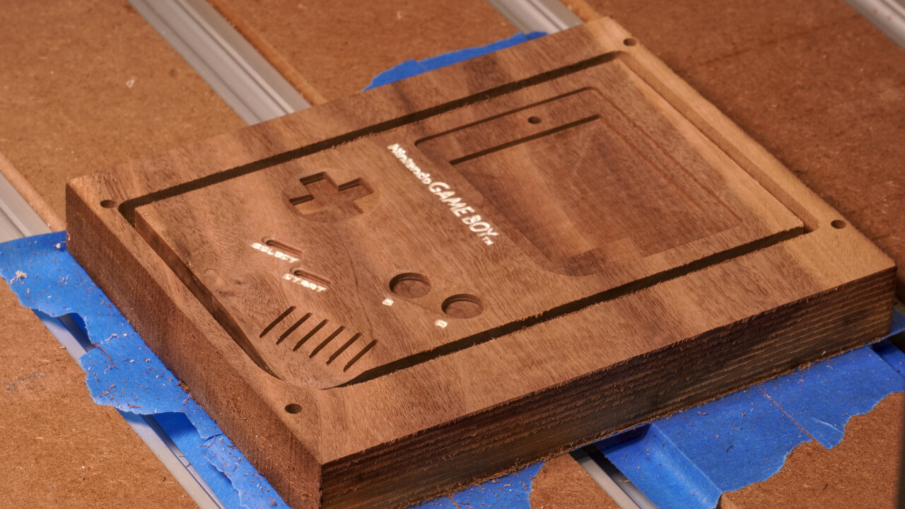
Outline chamfer
90° V-carving
003-top-outside-6-chamfer-90deg.gcode
2 min
Finally, my favorite step of most CNC projects. Chamfering. So satisfying.
Unfortunately, there is a mistake in my toolpath. While just following the outline works perfectly for most parts of the Game Boy front, I underestimated the effect of the slope at the speaker corner. A 45° chamfer towards this slight incline resulted in a bit of overhand and a slightly weird look. I sanded5 most of the problem away, but you might want to consider skipping chamfering in this corner.
C09
Purpose
Tool
Gcode
Duration
Detail decor lines
1mm upcut
003-top-outside-7-detail-1mm.gcode
3 min
The last step on the outside of the top half just adds the decorative fine lines to the front. This is quick and easy, but note that the only reason for using an upcut bit here is that I simply don’t own a 1mm downcut bit.
The inside of the top shell (D)
Once again it is time to flip your workpiece and align it. And once again remember to offset by 5mm if you use my method.
D01
Purpose
Tool
Gcode
Duration
Surfacing
Surfacing bit
N/A
81 min (depends on original thickness)
If you use wood from the same board as the bottom half of the shell, you probably have to remove a lot of material here. You are aiming for a final thickness of 14.5mm. And this one needs to be very precise. On the bottom half a too thick shell might make it harder to get the battery contacts through to the battery compartment, but on the top half this impacts the top position of your buttons, how deep the screen is below the window and whether your speaker grill goes through (spoiler: mine didn’t).
D02
Purpose
Tool
Gcode
Duration
Pocketing of most internal geometry
3mm downcut
004-top-inside-1-pockets-3mm-downcut.gcode
179 min
This is the massive pocketing job for the inside, covering most parts. Note that I took some liberty in optimizing the shape for a subtractive process. The original injection mold shape obviously tried to save material while we would like to save on carving away material. So in many parts I left a lot of wood in there, where the original Game Boy just has pockets of air. This should also make it more rigid.
D03
Purpose
Tool
Gcode
Duration
Details of internal geometry and speaker grill
1.5mm downcut
004-top-inside-2-details-1.5mm-downcut.gcode
15 min
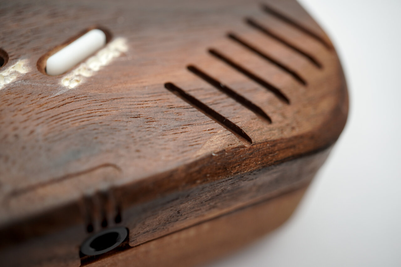
Adding details that could not be done with a 3mm bit in the previous step. Most notably some details around the buttons and the inside part of the speaker grill. Like on the original, the speaker grill is designed such that the lines on the outside just touch the ones on the inside to create openings. Unfortunately, this just did not work out on my build, but the sound can still be heard very well, so I am not attempting to tinker with it. However, you might want to keep an eye on the problem and maybe move paths closer together.
D04
Purpose
Tool
Gcode
Duration
Headphone jack
3mm ballnose
004-top-inside-3-phone-3mm-ball.gcode
3 min
Super short, super simple. The cutout for the headphone jack. I only used a ballnose because this is curved. If you want to save time, you could probably have just done it with a flat end mill in one of the previous steps.
D05
Purpose
Tool
Gcode
Duration
Profile cut
3mm downcut
004-top-inside-4-profile-3mm-downcut.gcode
5 min
Finally, the profile cut that meets the one from the front. Hopefully you aligned everything perfectly.
D06
Purpose
Tool
Gcode
Duration
Screw drilling
1mm upcut
004-top-inside-5-drill-1mm.gcode
4 min
This drills 1mm holes into the poles for the screws to tap in. As mentioned in step B03, the 1mm holes also did not work perfectly. In my opinion they are better than the 1.5mm holes I used on the bottom half, but the longer poles near the display were split by the screws in this case. If you come up with a better solution, I would like to know.
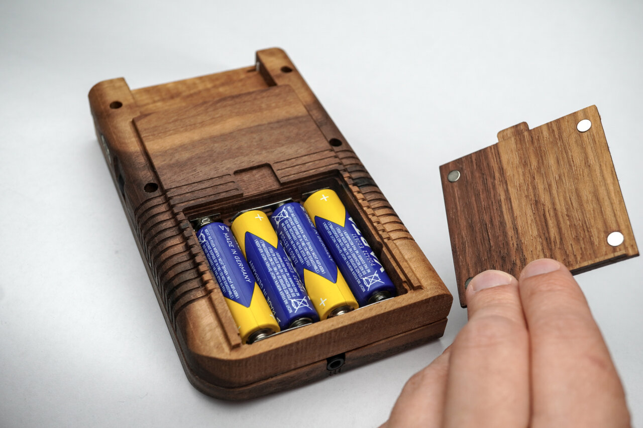
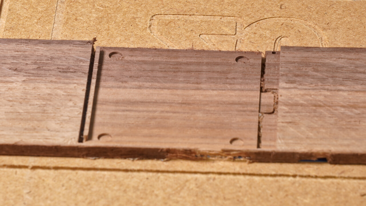
Battery cover (E)
Wait, we are not done yet. You still need a battery cover. However, since I did not see how the latch of the original Game Boy could be created with a CNC and survive more than one battery changes, I made a very simple design that uses magnets to hold the cover in place.
The battery cover is held in place by four small magnets.
So, this is a rather quick process and you only need a piece of wood with an even thickness of about 4mm to 5mm. The magnets should be 1mm thick discs with a diameter of 5mm and I could simply press them into the pockets.
E01
Purpose
Tool
Gcode
Duration
Reference for flipping
1.5mm downcut
lid_outside_0_references_1.5mm.gcode
1 min
Decor lines
1.5mm downcut
lid_outside_1_grooves_1.5mm_downcut.gcode
3 min
This step cuts references for flipping and adds the decorative lines on the outside of the battery cover. That’s it. Nothing more to see here and it is time to flip the wood piece to the other side.
E02
Purpose
Tool
Gcode
Duration
Cut down everything but lip
1.5mm downcut
lid_bottom-1-1.5mm-start4.5mmabove-bottom.gcode
42 min
Flatten handle
1.5mm downcut
lid_bottom-2-1.5mm.gcode
1 min
Magnet pockets
1.5mm downcut
lid_bottom-3-1.5mm.gcode
1 min
Profile cut
1.5mm downcut
lid_bottom-4-profile-1.5mm.gcode
2 min
This of course could have been one gcode file, but I couldn’t be bothered for this little part at the end of all the work. In this step you will flatten the cover to the desired thickness while leaving a lip that prevents it from sliding out. Here you also create the pockets for the magnets and do the profile cut, which will go below your workpiece into your spoil board.
Assembly
That’s it, the hard part is done. You should sand5 any problematic or rough parts and apply wood finish. I use boiled Linseed oil, but there are many options7 out there and many people with more experience in selecting them.
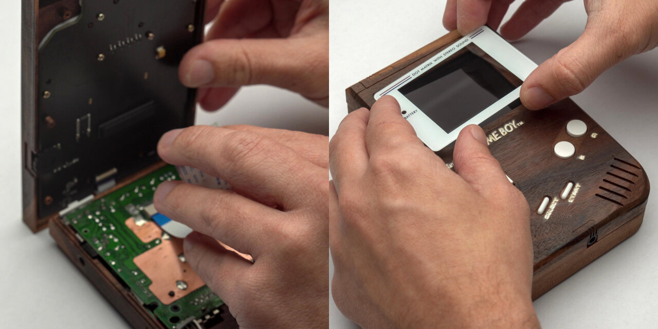
After that, you should be able to simply disassemble a Game Boy and replace its shell with your new wooden one.
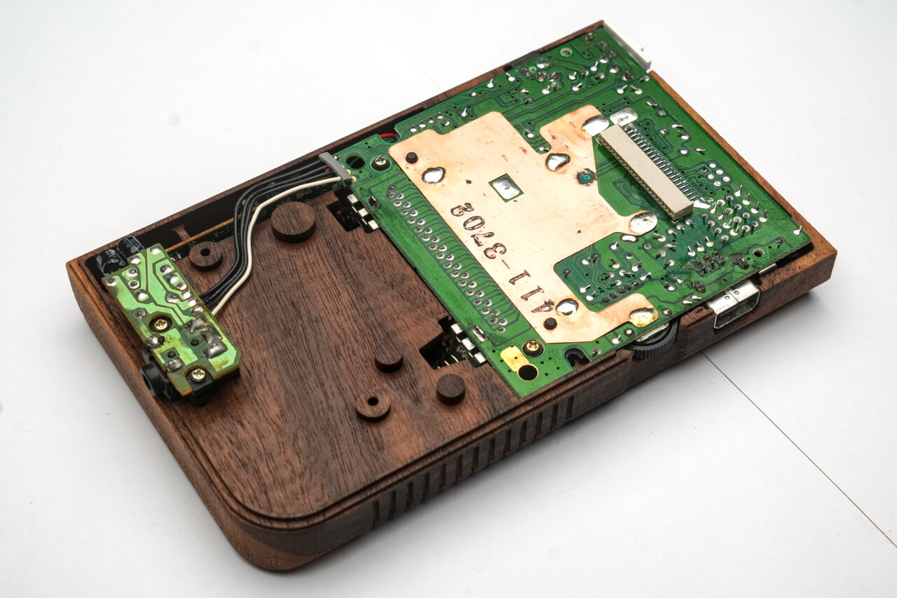
I actually only used the original mainboard of a broken Game Boy from ebay and aftermarket parts for everything else, so let me show you a few details.
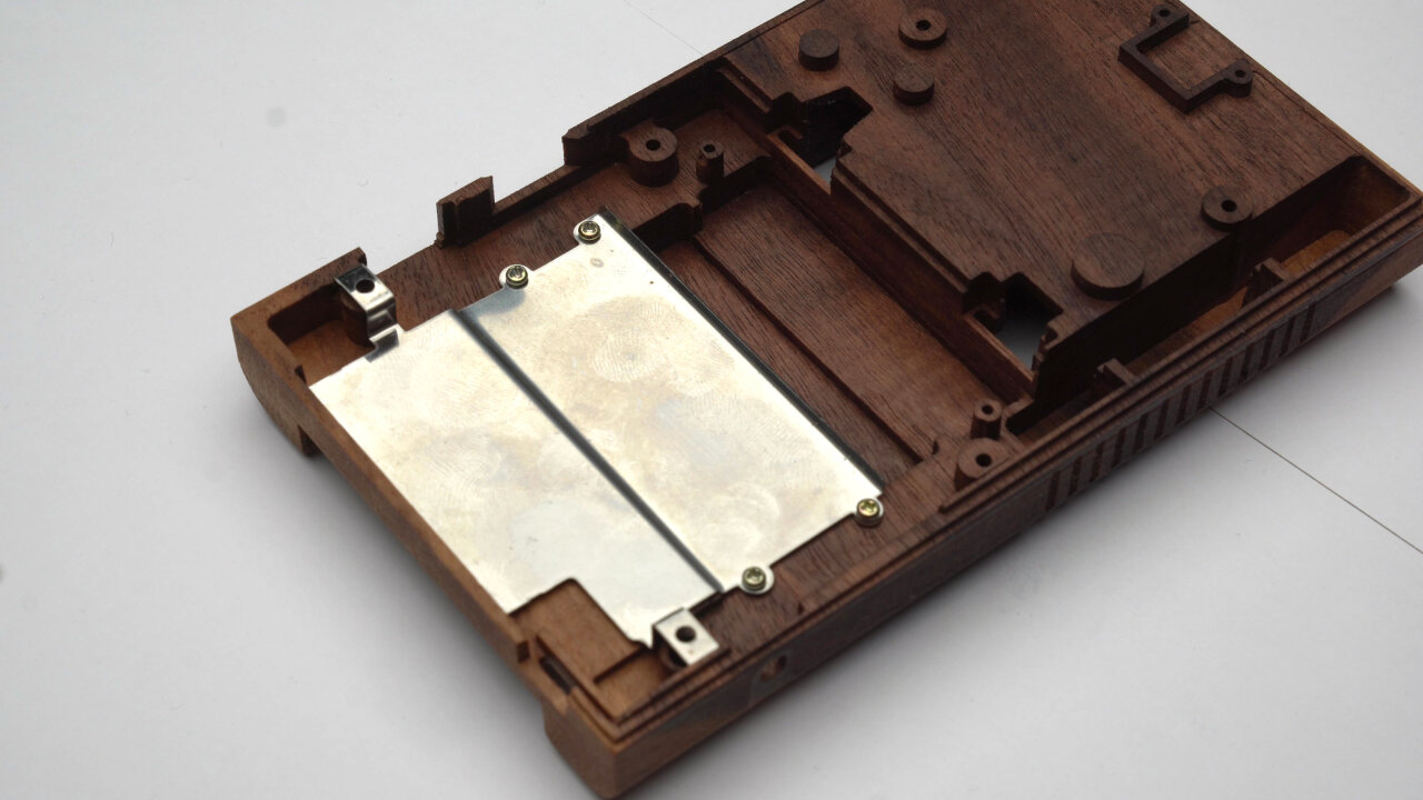
The original metal shield between cartridge slot and mainboard can simply be screwed into the wooden shell with the original screws.
First of all, the metal shield between mainboard and cartridge slot can simply be screwed into the wooden shell with the original screws (ok, those are also original parts). You just might need to file away some edges to fit the bent parts around the screw posts.
Bottom half with a mainboard and attached PCBs from an original Game Boy in place.
The same is true for the PCB and the attached boards. However, here I already had some problems of screws not holding well in the 1.5mm drills I did on the bottom half. The 1mm drills on the top half worked better, but posts tended to break there, so be careful here.
Contacts are simply pushed into the slits, but might need some padding.
In the battery compartment you just have to insert the additional contacts. The outer contacts are already there from the PCB. Note, that in contrast to the photo above I had to put a thin piece of cardboard behind the contacts to press them against the batteries.
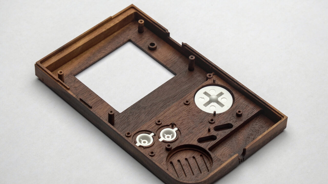
The aftermarket plastic buttons fit perfectly.
The white aftermarket plastic buttons fit perfectly, but there are some tricky aspects to the silicone pads between the buttons and the PCB. First of all, there are very thin poles that help aligning the silicone pads. They do not have to hold against any force, but still you should be careful to not break them as they really help putting everything together. Second, the silicone pad of the A and B button has a somewhat complex line around the buttons that looks roughly like a figure eight with an additional outline. I did not reproduce the slit for the additional outline, which prevents it from being flush on the wood by default. You either have to add a carving for the outline or cut the outline from the silicone pad like I did with my aftermarket pads.
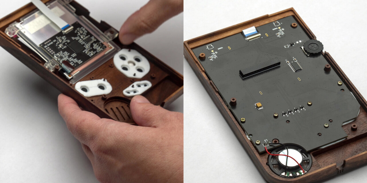
Left: Placing the IPS mod display with buttons and silicone pads already in place. Right: The display PCB of the IPS mod screwed into the top half of the shell.
For the display I decided against using an original screen8 and picked up a modern IPS mod kit instead. Note, that I made a few simplifications and optimizations to my design to fit this display. In particular, the contrast wheel has an additional lip on the original Game Boy and there are additional posts at the top of the display which I did not model. I think that an original display also fits, but you might look into this if you want to use a different screen.
I did not find a good way to add a small pole right next to the large pole in the bottom left corner of the display (viewed from the inside). Unfortunately, the plastic holder for the display that comes with the kit uses this pole as one of four poles that hold it in place. However, it still seems to be very stable when using only three of those poles. The PCB of the kit can simply be screwed into the shell with original screws and holds very well with the 1mm holes I drilled here. Only problem is that the poles below the display split in the process. So,… well… I am not sure what to make of this. The PCB is held very securely, but I am not sure if I will eventually find cracks in the case from the other screws over time.
Left: Both halves have to be connected with a ribbon cable. Right: Finally the glass cover from the IPS mod screen finishes the build.
Finally, all you need to do is to connect the two halves and glue the display cover into the screen bezel. There is just one major catch: For me the two halves were too tight and the screws could not properly hold them together. I am not sure if filing and sanding some parts for a better fit will help and if tapping the original screws into 1mm drill holes instead of the 1.5mm ones I have in the bottom half might be enough, but I only found a somewhat nasty solution: Gluing the case with wood glue.
Unfortunately, I had to glue both halves together, resulting in a slight gap and some glue residue.
While I still love the resulting Game Boy and while it feels very solid and reliable, it bugs me a little to have a slight gap on one side and a bit of glue residue. If I ever want to reach the parts inside, I probably have to crack the case open, but at least no original parts had to be glued and could simply be replaced in the original Game Boy. Still, it would be nicer if I could just open the shell in case I ever need to do maintenance inside.
Conclusion
When I started this project, I somewhat underestimated the amount of effort and time that had to go into it. But I also totally underestimated how stunning the result would be. At the moment it just sits on a sideboard in my office and I have to grin and pick it up each time I walk by it.
I totally love how precisely some of the iconic designs of the original Game Boy could be reproduced.
Initially, I planned to also machine the buttons out of a brighter type of wood. However, I did not find a good way to create a transparent display cover with matching wood applications and eventually settled for white aftermarket buttons and a matching display cover. Now that I see the result, I think that this was a good decision as it helps to define the shape and look.
Even though the speaker grill did not go through in my build, the precision of those lines as well as the headphone jack cutout, totally blew me away. Too bad that the white painted labels did not turn out so well.
Also, the Game Boy plays quite well. If I am looking for any playability problem, maybe the buttons trigger a little bit below their tactile response point and I am not entirely certain if this is to be expected. But this Game Boy will not be my daily gaming platform anyways. This is meant to be presented somewhere. At the moment I am thinking of making an acrylic stand for it and use my WiFi cartridge to use it as a status display in a prominent location.
The Game Boy plays well, but I still think it is meant to be a showpiece and not a travel companion.
Oh, and if you have been wondering about the wooden Pokemon cartridges: Those are based on the cartridge I published earlier with several improvements to the toolpaths (man, I learned so much from the Game Boy project) and the Pokemon logo added. These versions are also in the GitHub repository for the wooden Game Boy, but I did not add more documentation for it. If you got to this point, I am sure you can figure it out… :)
Even though I am a huge FOSS fan I am absolutely willing to pay for good software. But I am not willing to do so for software that does not even run on my OS of choice. I do not expect that CAMs are written for Linux, I just don’t want to pay several hundred bucks on software that then turns out to crash regularly due to emulation. ↩
Much longer than you would expect. The paths have to be closer to still overlap, but you also need to reduce the feed rate of your machine as the smaller bit cannot take as much material per rotation. Even worse: If you cannot increase the rotation speed, the smaller diameter also means that the tangential velocity of the cutting edges at the smaller diameter is significantly reduced. I would say that going from a 3mm bit to a 1mm bit will require about 9 times as much time to clear the same amount of material. ↩
Noticed the blue tape on my dust shoe? That’s where the machine drove the dust shoe directly down into a clamp from above. Did not stop or even slow down. After all, the motors are designed to press a mill into hard wood or even some metal, so it probably did not even notice the plastic cover of the dust shoe. ↩
Never used that word before. Hope I applied it correctly. ↩
My main reason for using Linseed oil is that I already used it as non-toxic option on things I made for my kids. I like the natural look of it compared to a clear coat, but that’s all the input I have here. I am not doing this long enough to say how well it protects my wooden Game Boy. ↩
In the past I made a point of using an unmodified original Game Boy to demonstrate that my hacks work with original hardware. No reason to that on a modded Game Boy like this. ↩
]]>There oughta be a bullet time video booth.2023-05-26T00:00:00+02:002023-05-26T00:00:00+02:00https://there.oughta.be/a/bullet-time-video-boothFor my cousin’s wedding I did not make a photo booth but a video booth. - With an array of DSLRs to create a bullet time effect.
Click the image to see the video on youtube.com.
Since this is a very visual project, you should really watch the video. This blog post contains the same info with more details, but those details are probably only relevant if you really want to recreate this project, which is not an easy thing to do.
What is a bullet time video booth?
The story of this project actually begins in 2017 when I created a video booth for my own wedding. At many wedding receptions you can find photo booths, which are simple camera setups with a remote trigger to allow guests to create some memories of the special day. Usually this involves silly props like hats, wigs and giant glasses and it is as much about creating photos as a memory as it is about the fun of being creative while doing so. …and for my wedding I mixed it up a bit by putting my Sony NEX-5T on a tripod and allowing guests to take short 5 second clips1 instead of static photos. Later I cut all the clips into one long video with upbeat music and we still enjoy watching this memory today.
My family enjoyed it so much, that one of my cousins used the same setup a few years later at her wedding and when another cousin planned his wedding for this year, he also asked for a video booth. But this time I wanted to try something new by adding a bullet time effect.
A very low-res demonstration of what the bullet time video booth creates. Please check the Youtube video above for a proper quality demo.
In case you never heard of it: The bullet time effect has been around for a while, but became really famous when it was popularized with the movie “The Matrix” from 1999. It really became a signature style for these movies and has been copied and reused so many times that it pretty much became a movie cliché. But while it can easily be recreated in purely rendered form like animated movies or video games, it is still quite involved and costly to achieve with real cameras: You set up an array of photo cameras, trigger them all simultaneously2 and play back the individual photos as frames of a video. The result is that the scene seems to be frozen in time while the camera moves around freely.
And here you see the problem for hobbyists. If you are not rendering the entire scene but need to take photos of real people, this can quickly become expensive. Bullet time-time costs one camera per frame. For someone shooting with the typical “European” 25 fps3 that’s 25 cameras per second. And that of course also explains why my bullet time video booth only uses this effect for the transitions instead of recording several seconds of bullet time footage. I simply wanted to keep the costs for this project in a reasonable range by only using twelve cameras.
This is the video booth as seen from the guest's perspective. (Well, if the guests were dwarfs.) You can clearly see that the cameras are placed at greater distances towards the wall to the left to achieve the impression of it accelerating to/from the wall when played back in sequence.
This means that I only have a bit less than half a second of bullet time footage per guest. But as you could see in the little example clip above (and more in the Youtube video) the effect is still nice and appears longer. To achieve this I used two tricks:
I trigger the cameras at the beginning and the end of each video recording and they are arranged in an arch towards the wall behind the guests. By mirroring every second guest clip and playing the bullet time photos in different order I can combine the two twelve photo sequences from the end of the previous guest clip and the beginning of the next guest clip to make it look like the camera spins through the wall to the next clip. An additional blurred frame at the location where the camera would be inside the wall and a non-equidistant placement of the cameras for an accelerating motion towards the wall help to sell the effect. This adds up to 25 frames and therefore one second of bullet time footage.
I created the final video of all guests (and the example above) in DaVinci Resolve and used its Optical Flow Estimation to generate artifical additional frames. This allows to smoothly slow down the bullet time effect further and also gradually slow down the video recording after leaving a bullet time transition and before entering the next bullet time transition.
So, I was able to pull this of with twelve cameras plus the one for the video recording. But this setup requires more than just the cameras…
Setup
In this section I will go through the important components of the bullet time video booth. Keep in mind that pretty much everything was selected to keep the costs as low as possible. Unfortunately, this also means that some components were a bad decision in hind sight and some components are simply more expensive or better equipment which I happened to already have. So, if you want to build something similar, be prepared to pick your own components and adapt the software to your needs.
Bullet time camera array
Let’s start by looking at the part that obviously is the most expensive because that purchase comes with a factor of twelve: The cameras used for the bullet time effect.
When I said that the bullet time effect is still expensive, I have to admit that it has become much cheaper since 1999. Cameras have become so readily available and good today that a comparison to 1999 equipment would be ridiculous. Still, I set myself a limit of 50€ per camera, which means that the twelve cameras alone would cost 600€, which I find quite heavy for a fun gimmick to a video booth4. And now think about what cameras you can get for 50€… There are some possibilities like webcams, used smartphones, used action cams, etc. But used ones for 50€ will have poor image quality and their small sensors are not ideal for this effect as they require more light for short shutter speeds or you will get a lot of motion blur. Raspberry Pi cams are also an interesting alternative in the maker world, but the cheap ones have very poor image quality and the better ones cost 50€ alone without a lens - and you need a few actual Raspberry Pis which are even more expensive.
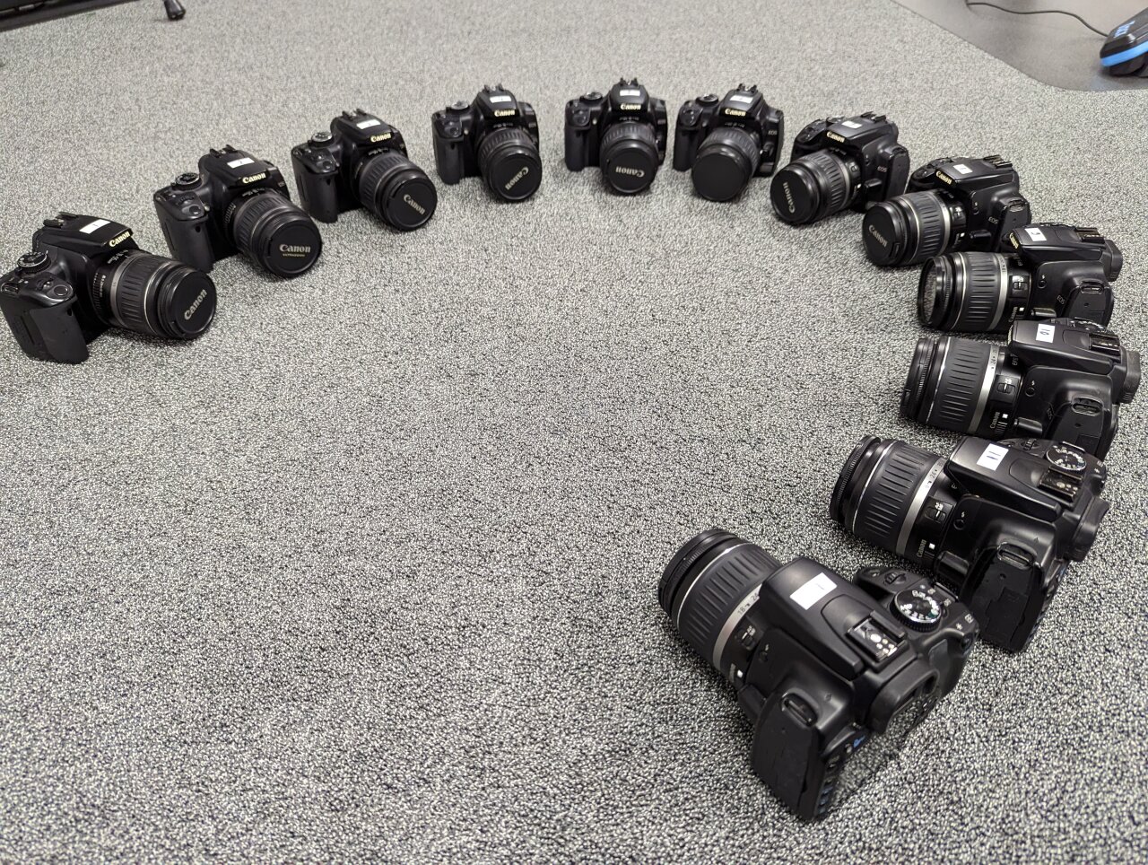
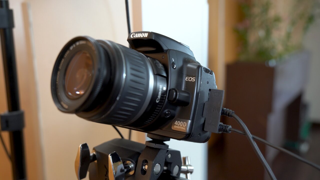
Instead, I looked for old used DSLRs. They have large (albeit old5) sensors, they support means to remotely trigger the shutter, they have plenty of resolution, their settings can be controlled precisely and nobody except me is interested in them anymore. The trick is that we are using the photo mode of these old DSLRs to create a video, which means that we are comparing old photo specs with modern video specs. So, I looked for the oldest mainstream beginner DSLR that has a decent resolution and picked the Canon EOS 400D6 from 2006.
Now I am the proud owner of twelve Canon EOS 400d...
That camera is now almost 17 years old, which means that craigslist7 is full of those cameras. There are so many people trying to sell their old camera with almost nobody being interested in such outdated technology8 that I could simply work through the offers starting with the oldest listings. I offered my 50 bucks for the 400D and its mediocre kit lens, reminded the seller that nobody has even looked at the listing in six months, and either he accepted or I contacted the next one in the list.
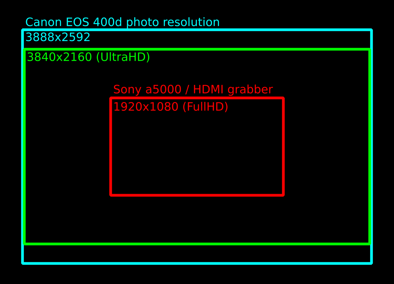
But is it good enough? Well, that’s where we can now compare the photo specs to the video specs. The old 400D from 2006 has a photo resolution (it cannot even shoot video) of 3888x2592 pixels, which is more than our modern 4k (or actually UltraHD) video with 3840x2160.
Video camera
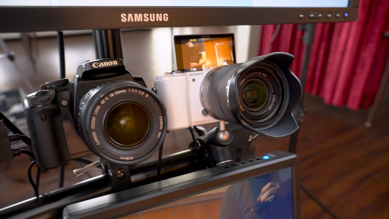
But since the Canons cannot record video9 I need one more camera as the main camera that shoots the video. Initially, when I selected the 400Ds, I aimed for 4k video and planned to use my trusted Sony a6400 for this. Unfortunately, it turned out to be rather difficult to trigger the video recording precisely and transfer the resulting video file. Both can be done via USB, but one requires the camera to be in control mode and the other one requires it to be in mass storage mode. Video files apparently cannot be transferred in PTP mode, which seems to be an oversight by Sony.
While the bullet time shots were done with Canon EOS 400d, the video was recorded on the Sony a5000 that some of you might know from an older post.
I either needed to use a Wifi SD card like I did in my old original video booth or record externally with an HDMI grabber. Since transferring 4k videos with a Wifi card (or maybe even recording to that old Wifi SD card) seemed like a bad idea, I dropped the 4k goal and went with one of my cheap 1080p HDMI grabbers instead. And since I did not need to tie up my good camera in this project if I only record 1080p footage through a mediocre HDMI grabber, I used my Sony a5000 instead. Some of you might remember it from an older post, because it requires a hack to get a clean HDMI signal.
Only the a5000 and the HDMI grabber limit the video booth's resolution to 1080p. And a rather low quality 1080p if I am honest.
So, we are down to FullHD, but as a plus using an old cheap camera gives me some valuable peace of mind when leaving the bullet time rig unattended at the wedding venue.
Quarter circle stand
At that point I thought that I had bought the most expensive part of my bullet time rig - until I faced the question of how to mount the cameras. Whichever solution comes to your mind right now: Remember to multiply its cost by twelve and think again.
Using twelve individual super-cheap tripods is impractical as someone will easily hit one of the tripod feet and misalign a camera from the other ones. So, I was sure that I need a common stand to which I mount all cameras. I first thought of traverse material as found on stage, but that is super expensive. The next idea was to build something myself out of plywood when I stumbled upon a B-stock e-drum rack. Specifically, it was a rack for the Alesis Strike Pro SE. On its own this is not ideal because its components are not enough to form a proper quarter circle and the horizontal bars are not mounted at the same heights. But I got that B-stock rack and a new one for a total of 93€ and combined them in a different arrangement. This even left a few spare parts that I could use to mount a screen to the setup.
This is a rather bad mounting solution. You can also see the crack in one of the threaded plates.
Unfortunately, that was not the end of the problem, because I still needed to mount the cameras to the rack. That’s where I went for a solution that was too cheap. I got cheap clamps from aliexpress (which were fine) and attached them to the cameras with simple threaded rods and cheap threaded plates. My thought was that twelve cheap ballhead mounts are quite expensive in total and that instead I could rotate the clamp around the rack bar and adjust the second axis by tightening the threaded plates. Unfortunately, I ended up just tightening the clamps to the cameras until the threaded plates cracked, which worked ok that one time, but if I want to use the setup again, I need to replace all plates - and probably buy twelve of those cheap ballhead mounts after all.
Power supplies
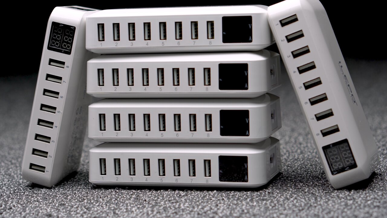
Another bad solution that I cannot recommend is the power supplies. You obviously don’t want to rely on batteries, so a set of dummy batteries from aliexpress had to be purchased (again, factor twelve - you see how this adds up?). For some reason I thought that getting ones that plug into USB ports instead of AC outlets would be a good idea, although both need to convert the voltage to the camera’s 7.4V. The tempting idea was that I could just plug all cameras into two 8-port multi chargers.
That was until I did my first tests and the cameras reset instead of taking a picture. At least when I triggered all twelve cameras simultaneously. Because in that case the chargers could not keep up with the sudden surge current and were unable to provide the proper voltage for the cameras. I think the problem here is that these old DSLRs need next to no power in standby as they do not show a live view. But when triggered, they have to move the mirror as well as the shutter while suddenly reading and processing the sensor - and they were designed with a Li-Ion battery in mind and not a cheap USB-based converter. The chargers on the other hand expect a more or less constant high current draw from a device that actually buffers sudden power demands with its own battery.
In the end I had to get six of those charger, which certainly was a rather bad solution to the problem of powering the cameras.
Regardless of the cause of the problem I tried many chargers and most of them struggled with the triggering cameras. In the end the multi-charger was the most reliable one if only two cameras were connected, so I ended up buying six of these multi-chargers, which of course was way more expensive and inefficient than using dummy batteries with individual AC power supplies in the first place.
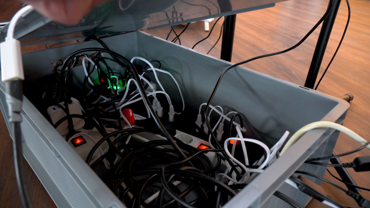
Most of the cables could simply be hidden in a storage box.
USB connections
And while we are talking about USB problems, the data transfer was not any easier. I connected the twelve cameras through two active USB hubs. I think this is close to the limit of what you want to manage as a large web of USB cables. Larger projects should instead use a few Raspberry Pis and connect via ethernet, but twelve cameras plus a Rapberry Pi Pico (see next section) plus the HDMI grabber (on its own USB bus) should be managable, right?
Well, it worked on a Raspberry Pi 3 which I first used as the brain of the bullet time rig. I had some electrical issues like the entire USB bus resetting when I turn on the fluorescent lights in my basement, but in principle I could control and read-out all cameras reliably. But since the Pi 3 was too slow to generate a preview in under a minute I replaced it with an old Dell XPS 12. And suddenly I could not use all USB devices at the same time.
After some research I learned that the Intel xHCI USB3 host controller in that device has a limit of 96 endpoints and that USB3 uses (at least) three endpoints per device. That’s still plenty? Well, don’t forget that each USB hub and all internal USB devices like the laptop’s Wifi module, Bluetooth module, webcam, sensor hub and internal USB hubs count towards that limit. In the end, after blacklisting some devices (no BIOS option to disable the webcam) I still had one device more than the controller could handle.
The solution? Connecting the USB3 hubs through a cheap USB2 cable. Seriously. That forced the devices into USB2 mode, reduced the number of endpoints and solved the problem.
Camera trigger
Ok, so at that point we have all cameras mounted, they have power and they can be controlled via USB. That’s it, right? Not necessarily. You can trigger the cameras via USB and that’s what I tried first. But I found that this was not reliable and precise enough and that some cameras would trigger with a minor delay. Not much, barely noticable from the sound of the camera shutters, but if you play back the photos as a bullet time clip, you would notice that some photos were taken at slightly different moments in time - at least if there is fast motion in front of the camera.
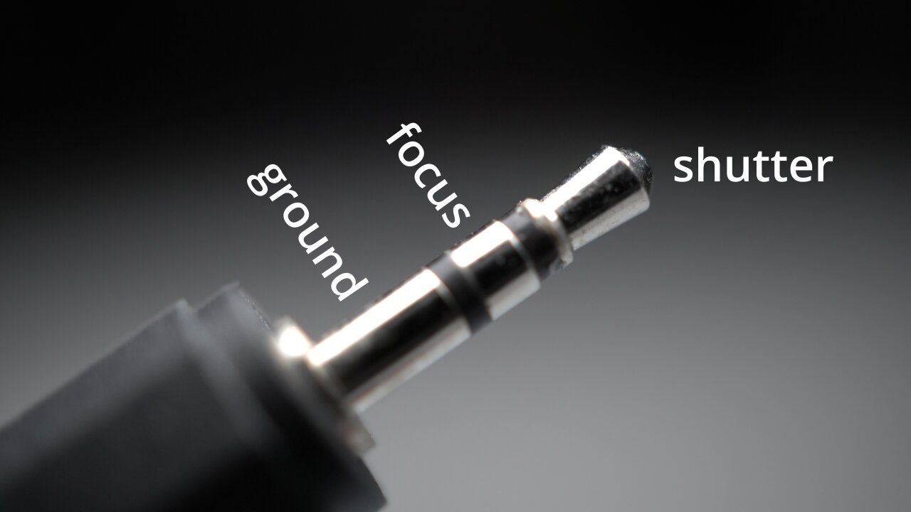
So, instead I used the trigger inputs of the Canon cameras. These are fairly simple: It is a smaller TRS audio jack with a common ground and two contacts that control the autofocus and the shutter. These two contacts are pulled up to 3.3V by the camera and if you connect them to ground they signal the camera to focus or to trigger, respectively.
The trigger cable for the Canon DSLRs is a simple TRS audio connector.
If you want to build a proper solution, you would now design a little circuit for each camera that decouples this electrically via optocouplers which in turn you control through some simple transistors and a GPIO pin of the microcontroller of your choice. If you are lazy, you simply connect all trigger inputs in parallel directly to the GPIO pin, set it to open drain mode to avoid it fighting with the camera’s logic level and let it drive all twelve pins to ground through a common connection.
I chose the lazy solution.
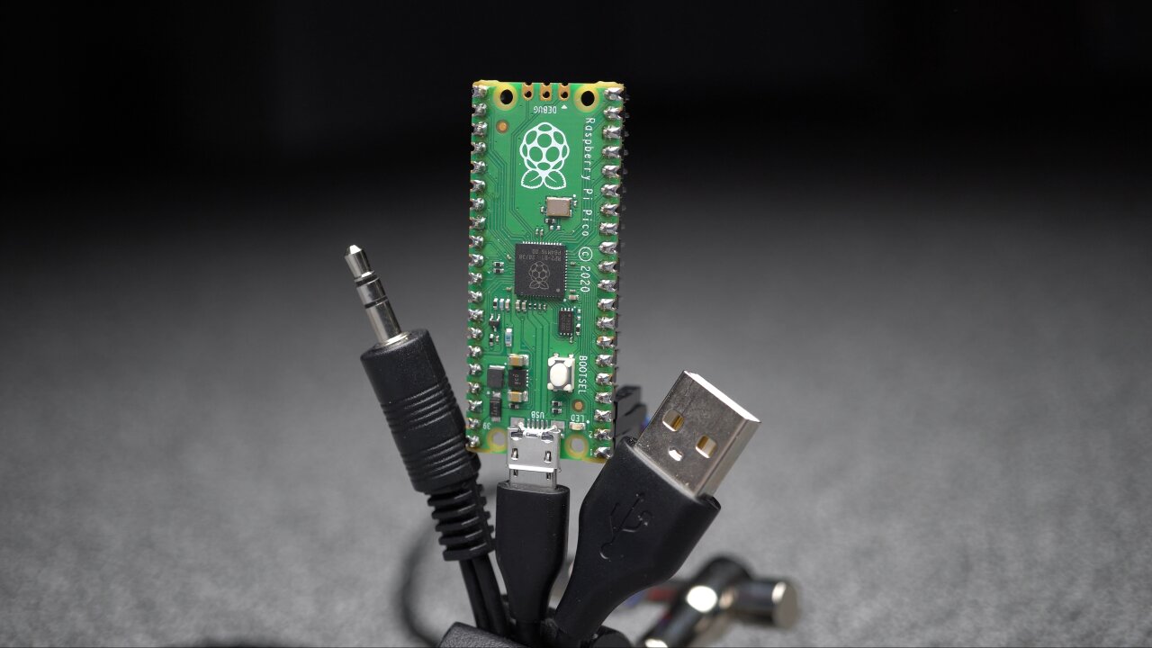
The Raspberry Pi Pico basically offers a serial interface via USB, which allows to pull either of the two signal lines of the trigger cable to ground.
The advantage of this is that you can use cheap audio splitters and a bunch of cheap audio cables to connect all twelve cameras. Everything, including the GPIO connection, is just connected in parallel.
The disadvantage is electrical issues as all camera logic levels are connected through their pullups and all grounds are connected through the trigger cables as well as the USB spaghetti and dummy batteries with their voltage converters and USB chargers. You can tell that this is not how these triggers are meant to be used when you notice that all cameras trigger randomly if one of the cameras is turned off. This is an electrical nightmare and probably also part of the reason that the USB bus resets when I turn on the lights. I cannot really recommend doing this. …but it works.
Oh, the code for the Pi Pico of course is as simple as it can get, but if it helps you can get it from my github repository.
Bluetooth push buttons
A part that I am actually somewhat proud of are the big push buttons. Not because they are such an intricate design, but because they are mostly a spontaneous solution that worked perfectly. I left them for the end of the project thinking that I just need to add cables and connect them to one of the many GPIO pins of the Pi Pico that also controls the shutters. But when I got to that point I was uncertain on where the buttons would be placed at the wedding reception.
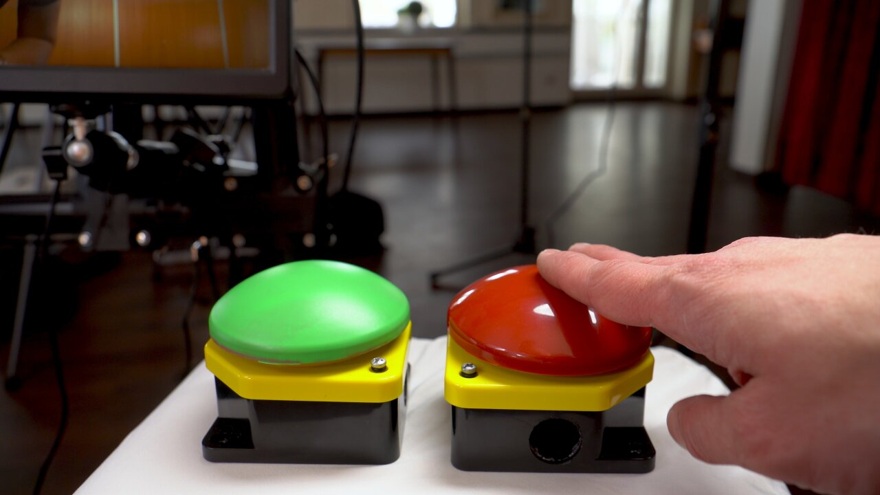
The green button is used to start the recording countdown and to confirm that a recording should be kept when the guests review their result. The red button discards a recording or aborts a countdown.
So, I spontaneously decided to make them wireless. And since I am not a fan of keeping a stock of Li-Ion batteries10 and also wanted to be able to have spare batteries available if necessary, I wanted to use good old AA batteries. So, I checked my stock of microcontrollers, ruled out the ESP32s which are a bad mix with AA batteries11 and found the Raspberry Pi Pico Ws that I bought with another electronics order and had not used yet.
These are cheap, can easily run on two AA batteries and have a Bluetooth module on board (like the ESP). They are also small and easily fit into the buttons together with the batteries. Only problem: Their Bluetooth module has only been implemented recently and it is still a bit tricky to get this set up. Also, Bluetooth is currently only available in the C SDK. But once I figured it out I had two big push buttons, running on AA batteries all night long. They connect to any device that supports Bluetooth Low Energy as a normal HID interface, i.e. they act as a normal Bluetooth keyboard that only has a single button.
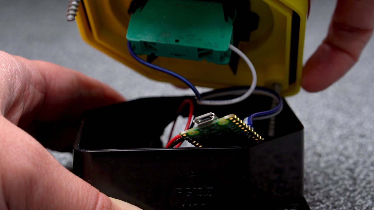
The Raspberry Pi Pico W fits easily into the push buttons together with two AA batteries.
Only bad news is that the licenses for the Bluetooth example that I used have not yet been adapted by the Raspberry Pi foundation. By that I mean that my code is based on hid_keyboard_demo.c of the Blue Kitchen Bluetooth stack, which is currently only referenced by the Raspberry Pi Foundation’s pico-examples repository. While some rumors speak of an upcoming maker-friendly license, the demo is currently only available under the Blue Kitchen license, which explicitly prohibits any redistribution for commercial purposes. Since I receive ad revenues for my projects (i.e. Youtube) I cannot claim that there is no commercial purpose and hence I am not allowed to share my code at this point.
If the code is eventually released under a more permissive license, please let me know and I will happily share the changes I made.
Until then, it is not too tricky to adapt hid_keyboard_demo.c. Connect the push button such that a GPIO pin is connected to ground by the button, enable the internal pullup of that GPIO pin and modify the demo such that a keypress is sent when the GPIO pin goes low.
Lights
Last but not least, you cannot neglect the lights. On one hand you want your shutter speed to be short enough to avoid motion blur from jumping guests. On the other hand you also do not want to use any auto-mode of the cameras. You want to avoid auto-focus, auto-exposure and auto-whitebalance, because the cameras would get different results and the pictures from each camera would be slightly different, which in turn would lead to flickering when playing them back in sequence.
So, you have to manually focus all lenses to a fixed spot and you either have to set the exposure and autobalance via USB for all cameras and automatically adapt it to changing light of the environment as the sun sets - or you bring controlled lights that dominate the other lights, so you can work with a fixed exposure and whitebalance through the entire day and night.
I already had a selection of video lights from the Aputure Amaran series and brought a 200d (200W COB LED light with a light dome attached), a 60d (60W COB LED light with an umbrella), an HR672C (larger LED panel) and two F7s (small LED panels). That won’t impress a professional videographer, but it’s a decent collection for a hobbyist and still I could notice some color shifts when the sun hit the windows of the room during sunset.
Oh, and don’t forget to think about the impact on the actual wedding reception. In this case I was lucky as I could set up the video booth in a separate room that was not used at that time and everyone became curious because of the bright white light that came from the door to the other room. But if you are in the same room as the dance floor, people will not be happy if you kill the mood by bringing your own personal sun without shielding it somehow. Just sayin’.
Software
Well, that was the difficult part. In contrast to some other projects, figuring out the cheap solution and getting all the hardware was indeed more time consuming than implementing the software. Besides the two minimal firmwares for the Raspberry Pi Picos (the camera trigger and the push buttons) the software only consists of a bit of Python code, which you can grab from my github repository.
As mentioned above, the brain of the bullet time video booth is an old Dell XPS 12. This is definitely not an ideal device here as it is an older convertible laptop without particularly impressive processing power. In fact, this might be one of the worst laptops I ever owned since I never really used it in tablet mode and it had a lot of shortcomings when you think of it as an expensive laptop12. But it was not in use and had significantly more processing power than the Raspberry Pi 3 that I tried to use first.
The thing is that this device shows the interface to the guests, which is either a simple countdown or an idle loop of previously recorded bullet time clips from other guests. But it also has to retrieve the photos from the cameras, record the stream from the HDMI grabber and convert the photos and that stream into video clips for a preview and that idle loop. On the Pi 3 it took more than a minute to create a 720p preview while the guests waited to see what they just recorded. On the XPS 12 it takes 20 seconds, which could still be improved with a newer device, but which is bearable for the guests.
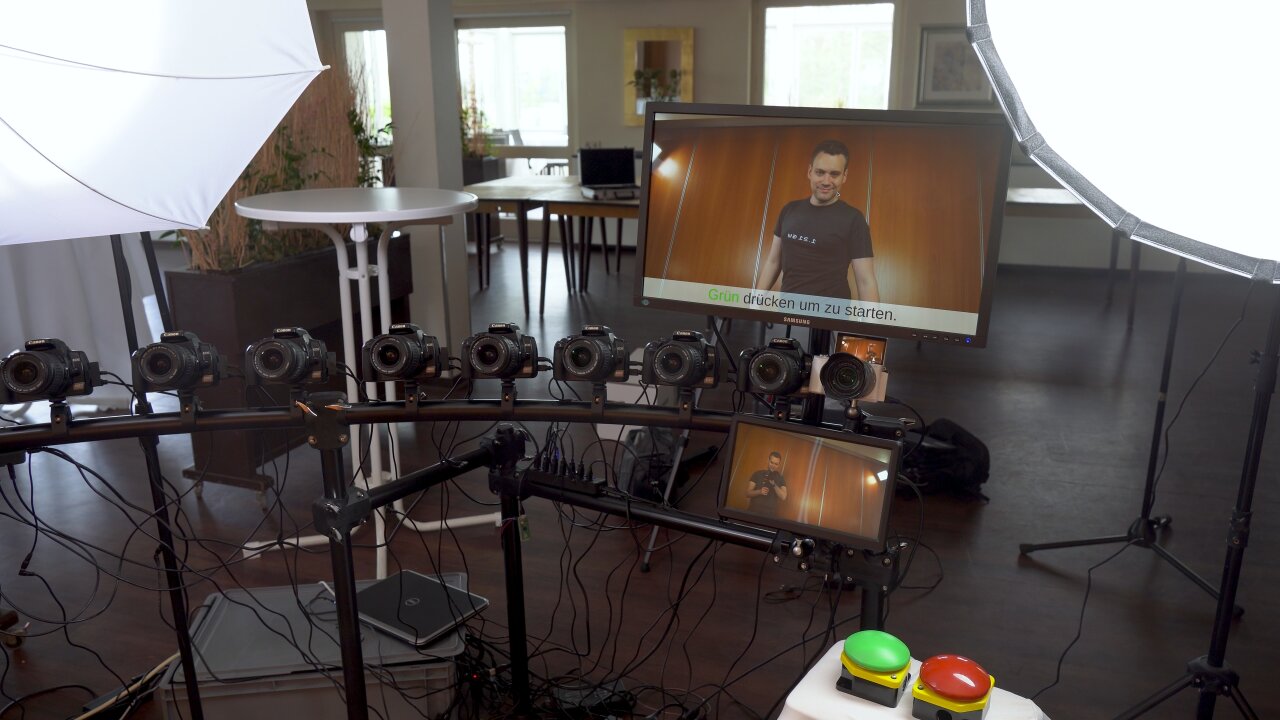
The upper screen shows a countdown, a 720p preview version of a new recording or an idle loop of already processed 1080p recordings. The lower screen shows a live view from the video camera (the a5000).
The conversion to video clips is not a simple concatenation in ffmpeg. In order for the bullet time effect to look good, the cameras have to be aligned perfectly, which is nearly impossible with the cheap mount solution that I picked. Also, you have to expect that the alignment will not remain perfect throughout the entire wedding reception as guests might accidentially bump into cameras13. So, instead of trying to achieve a perfect alignment, I made sure that the focal length of the bullet time cameras is a bit shorter (i.e. wider viewing angle), so that I can align and crop the resulting images later. This is the same as image stabilization for a video with the benefit that a misaligned frame does not come with additional motion blur. So, I used ffmpeg’s image stabilization for the clips that were generated on-site (preview and idle loop).
The filters in ffmpeg also came in handy to create what I call a “Pseudo in-wall frame”. That additional blurred frame at the location where the camera would be inside the wall, which I mentioned earlier. This is simply the photo from the camera closest to the wall, shifted slightly so that the wall is in the center of the image. A strong directional blur then masks the fact that the perspective is still far from the wall and only leaves a wall-colored smear that sells the idea of the motion blur that you might see if you could actually move through the wall.
The entire thing is implemented in Python and uses gphoto2 to communicate with the cameras via USB and an ffmpeg-wrapper module to generate the preview clips as well as the higher quality 1080p clips that are shown while the booth is not being used. The interface however is implemented in Flask and shown in Chromium. The reason for this is that the video players in webbrowser are among the best players in terms of performance and frame-precise playback. Since the clips are shown randomly during the idle loop they have to alternate between the mirrored and regular version and in order to sell the impression of the camera moving through the wall, the next clip has to start playback precisely on the last frame of the previous clip. This can be achieved with two HTML5 videos that alternate their playback state, so that one can preload the next clip while the other one is visible and playing. With one of the players being mirrored with a simple CSS transformation and without any noticable performance cost, the alternating flipping comes naturally in this system.
Post-processing
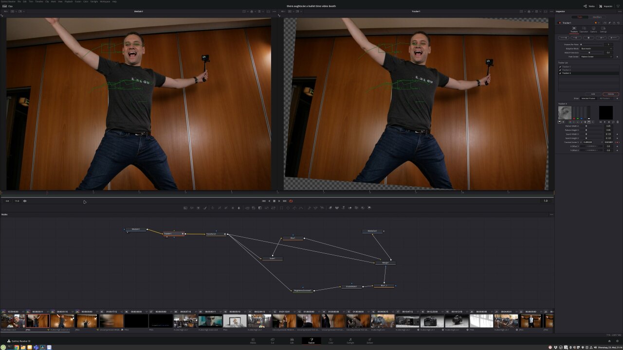
Now, there is one last step missing to get the bullet time clips from the preview above. The ffmpeg version only generated a rather generic image stabilization by trying to stabilize the entire image, which includes countering the apparent rotating motion of the camera. Instead we want to stabilize the central point around which the camera moves. This is something I had to do manually in post using DaVinci Resolve. I used a simple tracker and a bullet time clip in which a person stood quite precisely in the place that should be the pivot point for the camera rotation. I tracked some features on the person and stabilized them while also zooming into the footage slightly to avoid black corners around the repositioned images.
There is no reason to do this tracking for every clip, as the solution of the reconstructed camera motion can simply be applied to all other bullet time shots as long as the cameras have not been moved. So, I only had to do this three times for the entire footage from the reception when a guest bumped into a camera and changed its alignment. In the end there were some cameras that were so misaligned that black borders were no longer avoidable and I masked this with a blurry scaled copy of the orignal image behind the stabilized one.
Stabilization with simple trackers in DaVinci Resolve.
Another important processing step in DaVinci Resolve is adding additional frames. The one second bullet time transition generated with ffmpeg on-site already looked quite nice, but with optical flow estimation it is possible for many clips to add almost perfect additional artificial frames. So, I set up a slowed down version with Resolve’s Time Warp feature, which does not work for every scene and sometimes creates obvious artifacts, but which helped to really bring out the bullet time effect for scenes on which it worked nicely.
In the end my cousin’s guests recorded more than 100 clips, which I had to edit into a longer video. Luckily, DaVinci Resolve can be automated with Python, so I set it up to automatically generate stabilized versions of all recordings with different amounts of additional artifical frames. This means that I had a collection with different variants of each clip, so I could pick which version looked best and also which had the right duration to match different music tracks. So, of course, not every clip ended with a bullet time transition as slow as shown in the demo above. In the end, nobody would want to sit through a video with a hundred of those, but it helped to showcase some really cool transitions with airborne kids, flowing hair and flying items14.
Conclusion
At this point I have to say that the final video worked out even nicer than I had hoped for. In fact, the part that bugs me most in the end is that this ugly wood panel wall in the background really downgrades the final look, but that could not be helped. If there is a next time (as in another occasion, not as in that same cousin marrying again) I should prepare a backdrop. Before the actual wedding I was really worried that I would spend a lot of time debugging and fixing things instead of celebrating with my family, because there were so many things that failed during tests. In the end there are 13 cameras in a rather naive electrical setup and if any one of them got stuck or had any other type of problem, the shots would be ruined. I had to deal with loose memory card covers that turned off a camera, a lose contact in one of the dummy batteries, some cameras dropping out due to a bad USB cables and of course all the troubles I had until I had enough power supplies to get a somewhat stable voltage when the cameras are triggered.
I got really lucky that none of this happened on that particular day. I had included a simple recovery code that detects unresponsive cameras and tries to reconnect the USB hub with all the cameras while warning the guests to wait a minute or call me if the issue persists. According to the recordings and what I heard from the guests this happened once, but I did not have to personally tend to it even once.
Still the point is that you should not try to set this up for your own wedding. Someone with some spare time and the appropriate knowledge should be ready to spontaneously fix things, which usually does not apply to the bride or groom. If you want this for your wedding, ask a nerd friend to look after it and if you want to build this for a friend, make sure that you have time to fix things on site.
But if it works, this is a fantastic alternative to the traditional photo booth. You can be sure that guests have never seen something like this before (well, unless my Youtube video becomes more succesful than I would expect), they will have a lot of fun posing in front of the camera array and playing with the bullet time effect (especially later in the evening) and the happy couple really enjoys watching the result and sahring it with their guests after the wedding.
The NEX-5T has extremely limited interfaces to start recordings and retrieving the results. So, that video booth used a DIY infrared remote to control the recording and a Wifi SD card to retrieve the results and display them to the guests. ↩
Actually, not triggering the entire array simultaneously can also be interesting. Depending on the timing of the cameras and the order in which you play the individual frames a number of different effects can be achieved where time does not halt but only slow down, reverse or speed up. ↩
Of course, with digital cameras and when publishing the footage to Youtube the technical reasons to pick one of the common framerates (24fps for cinema, 25fps for PAL, 30fps for NTSC) are so weak that many consider this to be an aesthetical choice. But after I came back from a trip to New York City to notice that all my recordings at night were flickering badly because of the street lights using the typical US 60Hz power grid, I have a strong preference to make sure that the local power grid frequency is a multiple of my frame rate. ↩
For me this is a mixed calculation. My Youtube channel has grown enough that I can expect some returns although I would be surprised if the revenue could cover the entire project. The rest is attributed to a favor for my cousin and the child in me who always wanted to play with the bullet time effect. ↩
In this case “old” has the consequence of significantly more noise at higher ISO settings. This is indeed a problem as we want fast shutter speeds. But in my experience the old large sensors are still better than any non-flagship smartphone camera with its tiny sensors. (And actually also the flagship ones, but since everyone just looks at the AI-enhaced photos on the tiny screens, not making that distinction will only provoke comments from users who refuse to believe that there is a difference between a 1000€ phone and a 1000€ camera.) ↩
Also known as Canon EOS Kiss Digital X in Japan and Canon EOS Rebel XTi in the US. I would like to talk to someone from Canon’s marketing department about this… ↩
I probably consume too much US content, but it feels wrong to mention a different site while writing in English. Of course, it was not craigslist, because we do not have that in Germany. It was “ebay-kleinanzeigen”. (Which is no longer owned by ebay and just dropped the “ebay” in its name a few weeks ago.) ↩
Also not outdated enough to be bought by Hipsters. ↩
Even if they could: That’s where their age would certainly show. ↩
It’s a personal habbit of trying to avoid old forgotten Li-Ion batteries after my wife’s laptop battery caught fire in the middle of the night. ↩
The ESP32s are fine, but the common development boards don’t have a voltage converter that would be able to run on 3V. So, you have the choice of using three AA batteries and a dropout when they are half empty or four AA batteries with fairly high losses. ↩
Not to mention that shortly after I stopped using it the display leaked some goo that messed up the inside and keyboard and ruined the display itself. ↩
I noticed two times in post processing when the camera alignment changed and could actually find the exact clip of when it happened. After all there are ten or more people squeezing into that quarter circle trying to show some action for the recording, so I am surprised that it did not happen more than twice. ↩
Unfortunately, I cannot show any of those. I would not show a person without their consent and decided against asking random guests if they would want to appear on Youtube. So, you only get to see my closer family and only those who answered to an open “who volunteers their clip?” question without me pushing this on anybody. ↩
]]>There oughta be a Q&A about the GB Interceptor.2023-02-21T00:00:00+01:002023-02-21T00:00:00+01:00https://there.oughta.be/a/q-and-a/q-and-a-gb-interceptorI collected your questions about the GB Interceptor and made a very long video taking my time to answer them.
Click the image to see the video on youtube.com.
And sorry if this pops up in your RSS feed several months later. I simply forgot to add a blog entry for this and backdated it.
]]>There oughta be a Game Boy capture cartridge.2022-12-20T00:00:00+01:002022-12-20T00:00:00+01:00https://there.oughta.be/a/game-boy-capture-cartridgeI present to you: The GB Interceptor. It is an adapter that goes between an unmodified Game Boy and the cartridge and offers a video stream of the game via USB.
Click the image to see the video on youtube.com.
The video above should give you a good overview of what it does, how it works and what its limitations are. This article here goes more into the technical details of how it works. If you are interested in how to order and build your own GB Interceptor, check out github and the order and build video.
Why do we need this?
The best way to explain why1 I developed and built the GB Interceptor is to explain which problem I tried to solve with it. A few months ago a Tetris enthusiast got in touch with me about this problem: An online Tetris tournament during which the contestants stream their gameplay.
Today, there is nothing unusual about streaming footage from a Game Boy. Emulators can easily do it and modern Game Boy variants like the Analogue Pocket offer HDMI output that could be captured. There also are some mods to add HDMI out to original Game Boy hardware, so getting a video stream from a Game Boy is a challenge that has long been solved.
The unusual detail about doing it for a Tetris tournament is that the players have to rely on their muscle memory which they trained on their personal Game Boys. Switching them for an unfamiliar modern device or an emulator will significantly impede their ability to play competitively. Also, you can imagine that a tournament that asks each contestant to first mod the hell out of their beloved Game Boys just to stream a video would not be well received.
So, we need a way to get a video from unmodified Game Boys also without modifying the game that is being played. Ideally in a form that can be used by anyone without complicated software or additional hardware like an HDMI grabber.
Basic concept of how it works
Well, in the end, the only connector with game data that is accessible on a Game Boy without a mod is the cartridge slot2. After all, the entire game data has to go through there. So, the idea is to create an adapter that connects the cartridge to the Game Boy directly and only adds the capability to intercept a copy of the transferred data.
The GB Interceptor connected to a laptop, which shows its video stream in VLC.
However, this means that we cannot randomly access data of interest and we cannot see the data in RAM that the Game Boy’s CPU put together from the raw instructions from the cartridge. Especially, we cannot see the Video RAM, which would have been very nice as it would contain everything3 required to draw the image on screen. Instead, we need to create our own copy of VRAM.
To do so, I had to write an emulator to which I feed the data from the cartridge memory bus. For this I use an rp2040 (the Raspberry Pi Pico’s microcontroller) and split its cores to the two main processing parts of the Game Boy. One core emulates the CPU to recreate a copy of VRAM and the other core emulates the Game Boy’s graphics unit, the PPU4.
The CPU emulation actually is the trickiest part here, because it has to keep up with the memory bus that is pushing out events at a rate of about 1 MHz. If the PPU emulation falls behind, it would cause a short glitch like a flicker, but if the CPU emulation falls behind, it will eventually miss an event on the memory bus. Not only would the simulated copy of the RAM possibly get out of synch forever, but the emulator would not even be able to interpret the following instructions. An event on the bus is not always the next instruction, because the Game Boy’s CPU may take several cycles to execute some instructions while others are completed within a single cycle. So, the emulator has to keep track of how many cycles have to be ignored after a specific instruction before an event should be considered to be an instruction again. If we miss only one of them it becomes nearly impossible to get this right again.
This together with the overhead of emulating an 8-bit CPU on a 32-bit CPU made it necessary to overclock the rp2040 from its default 125 MHz5 to 225 MHz. The rp2040 can usually handle this without any problems, but still I would love to see if someone can improve the efficiency of my code to dial this back a bit.
Since the PPU emulation is not that critical and actually periodically gets some free time during the Game Boy’s vblank period when no image is being drawn, it also handles USB communication.
The hardware
The actual hardware to implement this is pretty much a Raspberry Pi Pico with some bus transceivers to connect its GPIO ports to the cartridge bus. From the 32 pins of this bus, two are used for +5V and ground, one is used for analog audio6 and one is used to control the reset state of the Game Boy. The other 28 pins are connected to the rp2040, which therefore gets access to 16 address pins, 8 data pins and the four bus control pins clock, read, write and chip select. Since these use 5V logic I use the same bus transceivers that already served me well in the WiFi Game Boy cartridge to convert the signals to 3.3V for the rp2040.
This leaves two GPIOs unused. One observes the voltage on the +5V line to check if the Game Boy is turned on or not and the other one controls a status LED and reads a mode button.
The GB Interceptor's PCB with rails and a break-out board that have to be removed using it.
The rest of the cartridge is based on the minimal hardware design example for the rp2040 by the Raspberry Pi Foundation. This includes an oscillator, flash memory, a voltage converter and a USB port, which I replaced by a Type C variant.
That’s pretty much it. A Raspberry Pi Pico in Game Boy cartridge format hooked up to the Game Boy’s memory bus. The schematics and PCB designs can of course be found in the project’s github repository.
Implementation
What really let’s the GB Interceptor do what it does is its software, which can of course also be found on github. In the following I will write about some of its details.
USB video class
The GB Interceptor streams the resulting image using the USB video class implementation of TinyUSB, so in theory no drivers are needed and it should just show up as a webcam. Well, in theory. Unfortunately, this only works as expected on Linux, where I can directly use the GB Interceptor in VLC, OBS, Zoom or ffmpeg. On Windows and Android many apps seem to have trouble with the format of the video stream. On Windows, for example, VLC (despite working on Linux) complains that no suitable format could be found while OBS works perfectly fine without any settings or drivers required. On Windows this is good news because you can use OBS as a virtual webcam to forward the GB Interceptor stream to any software that is picky about the format. A list of tested host software can be found on github.
Unfortunately, at the time of this writing I was not able to get any video on MacOS and I am not yet sure why. For some reason it does not even trigger TinyUSB to enable the video stream, so I am not entirely convinced that it is the format. Keeping in mind that I have not yet done many tests on MacOS and that the video class implementation in TinyUSB is very recent and experimental, I hope that I can fix this in the future. Even if I could not get the video class to work here, it should be possible to pump the images through UART on the USB bus and use a simple Python script to convert it to a video stream on the system. You can check the current state of this issue on github.
So, what is that unusual format? Well, obviously, this starts with the Game Boy’s resolution of 160x144 pixels, which I can imagine might surprise some software expecting a modern 1080p stream. But it gets a bit more complicated when we look at the limitations that arise from the rp2040’s Full Speed USB port and its implications for the isochronous transfer implemented by TinyUSB. This combination means that the maximum buffer size for this endpoint is 1023 bytes and since isochronous transfer happens every 1 ms, we get 1,023,000 bytes per second.
If we just look at the raw image from the Game Boy, this is more than enough. The Game Boy has a “color depth” of 2 bit, so one image frame is 5760 byte. With roughly 60 frames per second we only require 345,600 bytes, which is why I see a custom UART protocol as an interesting alternative on MacOS if all else fails.
However, we do not want to need a driver or additional software. We want something that just works and unfortunately there is no 2bit color format that is widely accepted. Instead, there are plenty of compressed formats for which we do not have enough computation power left7 and some uncompressed color formats that are considered to be widely supported, most of which use 16bit per pixels. Instead we use a supposedly also widely supported slightly more efficient format: NV12 with 12 bit per pixel. The 12 bit are comprised of 8 bit per pixel for luma (grayscale brightness) and 16 bit shared by four pixels (hence 4 more bit per pixel) for the color information.
The good news is that the color data of the entire frame is stored at the end, so we can set it to gray or green once and can ignore it. In fact, we can treat the data before as a simple 160x144 pixel buffer with 8bit grayscale data, which is more or less ideal for our purpose.
The bad news, of course, is that it still takes up 6 times as much data as the original 2bit image would have needed. With our 1,023,000 bytes per second we are now limited to 29fps.
So, overall we have a 29fps NV12 stream at a resolution of 160x144. Not exactly what all those video conference tools expect.
By the way, although the GB Interceptor therefore only pushes out 29fps, it still works internally with 60fps and blends these frames to emulate the latency of the old LCDs. It just pushes out the latest blended frame whenever the USB bus calls for it.
Programmable IOs
Now after I explained how to get the result out from the GB Interceptor, let’s talk about the other end: How to get the communication on the cartridge bus to the rp2040.
Remember how much I struggled with my WiFi Game Boy cartridge when I tried to listen to a single event with an ESP8266? Interrupts were too slow8 and keeping the CPU in a tight loop observing the clock line was not an option. Well, the rp2040 has a trick up its sleeve: Programmable IOs. These are simple state machines that can directly access the GPIO pins as well as a FIFO buffer to/from the CPU. And these PIOs simply laugh at this task.
All we need to do is wait for the clock line to become low and then simultaneously read the remaining 27 GPIO pins that are connected to the Game Boy’s memory bus and write the result to the FIFO. For this we only need a single PIO and that executes only four instructions:
1
2
3
4
    wait 1 pin 28 ;Wait for CLK to go high
    wait 0 pin 28 ;Wait for falling flank of CLK
    mov isr pins  ;Read all GPIO pins to the input shift register
    push          ;Push the ISR to the FIFO
From there, the CPU can just pick up one of these events packed into a single 32 bit integer from the FIFO whenever it is convenient.
The emulator part
Now it is time to talk about what these events look like. Or rather, how we need to deal with them. At this point I expect that you have a basic idea of how the Game Boy works. For those who are not familiar with Game Boy development I always recommend Michael Steil’s “Ultimate Game Boy Talk”.
As explained above, the basic idea is that one core of the rp2040 interprets the incoming bus events such that it follows the same instructions as the Game Boy’s CPU. That is, it emulates the Game Boy CPU in order to recreate an exact copy of VRAM (and OAM). The second core then acts as the PPU and renders an image from our VRAM copy. This is mostly just the implementation of a basic Game Boy emulator, but there are some differences that I would like to talk (or write) about.
Conditional jumps and IO
First of all, there are several things that become much simpler in this scenario. Think about the program counter and conditional jumps. We do not have to implement those. The real Game Boy fetches the next instruction anyways. It does not matter if it is the next instruction by incrementing the PC or if it jumps to an entirely different address. The real Game Boy will fetch the next instruction and we do not have to care about where the instruction came from.
This solves one of the seemingly biggest issues: We cannot see any of the hardware I/O registers. In particular, we do not see the input from the game pad! How should we ever emulate a game if we cannot see the player’s input? Well, almost every code in existence will compare the gamepad input to check which button was pressed and make a conditional jump to code that is triggered by the button. Our emulator will simply follow these same instructions and does not have to care whether it was triggered by a button press.
You could say that the GB Interceptor is an emulator on rails.9
This only becomes a problem if the data from the I/O registers eventually ends up in VRAM. Imagine that the value of the gamepad is added to a base address to calculate the tile index to an image that shows the current state of the D-Pad. The CPU would get the instruction to fetch the gamepad register value, add a number to it and our emulator would not know the correct result of that operation. This result is then written to VRAM and we have no idea what is in that location.
However, these should only amount for small visual differences. I do not know of any example where this is done with the gamepad I/O, but I have an example for the DIV register. In Tetris it is used as a source for random numbers and most of the time it branches the code through conditional jumps to pick different blocks that come next or to generate the initial pile of garbage blocks in game mode B. We do not see that random number, but when it triggers the code to logically pick the upcoming block, we will still get the same block as we get to execute the same code. This also goes for the decision whether a block of the garbage pile in mode B is empty or filled, so we also get the same layout for the garbage stack. But those garbage blocks also have a randomized visual style and that is not based on branching code, but just a random number added to a base tile index.
The result is that we see the same garbage stack layout on the GB Interceptor, but the individual blocks have a different look. This is harmless and you would only ever notice if you compare the image to the Game Boys screen.
Left: Photo of original Game Boy screen in Tetris mode B. Right: Same scene as rendered by the GB Interceptor. The layout of the garbage stack is identical, but the individual blocks have different designs.
We only get into real trouble when an entire stream of prepared data is written to VRAM from one of the I/O registers. The only example that I know of (and that I can think of) is the link cable. Here, we can look at the same example of the mode B garbage stack, but in two player mode of Tetris. The problem is that both players should have the same garbage stack. So, the Game Boy that starts the game first will generate that stack and send it to the second one via link cable. The second one writes the data directly to VRAM without any checks or conditional jumps and we cannot see anything.
Tetris in two player mode. Left: The Game Boy Color with the GB Interceptor started first and the garbage stack is rendered like in 1 player mode. Right: The other Game Boy started first and we cannot see the garbage stack as it has been received via link cable.
Therefore, in two player Tetris, the GB Interceptor works fine if it is in the Game Boy that starts the game first (except for the different visual style of individual blocks), but it produces unusable output if it is in the second Game Boy.
Clocks, the DIV register and the halt instruction
Speaking of the DIV register, this is actually an I/O register that we might be able to emulate. Since we get the exact clock from the Game Boy we can count an emulated register in synch with the real one without any danger to diverge. There are only two problems:
The initial value is unknown - at least to me. When the code from the cartridge is executed, the state of the DIV register depends on the Game Boy model and in some cases it also depends on the user interaction during the boot sequence of that model. For example, if you change the color mode of the Game Boy Color during the boot sequence, the DIV register will have a different value at the beginning. I am not sure if the Interceptor sees enough action on the bus during the boot sequence to compensate for that, but I also would not rule this out entirely.
We lose the reference clock when the Game Boy enters the halt state, which for most games happens at least once per frame. Here, the clock of the rp2040 has to take over precisely, which should be possible if we had a little bit more computational headroom. (i.e. if someone can optimize my code)
The thing is that we actually measure how many rp2040 clock cycles occur for each Game Boy clock cycle during the boot sequence before the actual game starts. Here we can observe thousands of cycles and should be able to get a very precise substitute clock from our rp2040. Unfortunately, for performance reasons, I only use an integer ratio of both clocks, which typically is in the order of 225 rp2040 clocks per Game Boy clock. This means that just the rounding error will lead to an error of roughtly one cycle per 100 cycles during a halt state, which happens regularly.
So, maybe we can do a fractional clock count, but for now as it only affects the div register which I cannot properly initialize anyway, this is not implemented.
Synching CPU and PPU
While we are on the subject of synchronizing our emulator to the real Game Boy… We of course also need to synchronize our PPU to the one of the real Game Boy. Otherwise any effect that requires changes in the VRAM midframe would lead to glitches and at least we would see some tearing effects as data is updated in VRAM randomly.
The problem is, that no trace of the PPU can be found on the memory bus. We have to deduce the state of the PPU by the behavior of the game, which has to synch to the PPU as well - at least to know when it may write to VRAM. The big problem here is that games can use many different ways to do so.
The most common method, is the vsync interrupt. Most games simply let the Game Boy trigger an interrupt when vsync is reached and we can see when the code of this interrupt is being executed, so we can simply adjust the timing of our own emulated PPU to enter vsync at that same moment.
Unfortunately, there are many other options to do this. Another common one for games that need to squeeze out a bit more access to VRAM (for example implemented in Donkey Kong Land) is to read the LY register in a tight loop and to periodically compare it to a specific line number. A conditional jump jumps back to the LY readout until the correct line is reached and the code simply goes beyond the conditional jump. Luckily, the developer can save a few cycles by jumping while it is not reached, so many games do it this way, which allows for a simple and naive detection of these tight loops in the Interceptor.
However, there will be games out there with a different approach (like my Wifi cartridge) and the output of the GB Interceptor will look glitchy until a detection for these other methods has been implemented.
Detecting interrupts
Oh, and while interrupts are a blessing to synch the PPU, these are not exactly easy to detect in the first place. We need to keep track of every single instruction and how many cycle the Game Boy needs for each instruction to be sure which event on the memory bus would be the next instruction. The Game Boy jumping to a different point in the execution and taking a few extra cycles to do so is not exactly helpful here.
Have a look at the first vsync interrupt of “The Legend of Zelda - Link’s Awakening”10 on the original Game Boy:
When ignoring interrupts, we would falsely interpret 0x3e in line 7 as an opcode. The only way to be more or less sure that we are seeing an interrupt is by implementing the GB Interceptor such that it reads ahead11 a few cycles to recognize an interrupt before the current event is misinterpreted as an instruction when in truth it is just garbage on the memory bus while the CPU takes a moment to enter the interrupt.
Luckily, the Game Boy jumps to few fixed addresses during an interrupt, so we look out for those. But since these addresses could theoretically also be called from regular code, we mix in a few more indicators, specifically the behavior of the stack pointer. During an interrupt call, the current PC is pushed onto the stack, so the SP register is decremented twice and the Game Boy writes to the two decremented addresses. Usually these do not point to an address belonging to the cartridge, but these addresses are still visible on the memory bus, so this adds to our confidence to detect an interrupt.
The only trouble with this is that the Game Boy is not really required to do this consistently and to show the SP address on the memory bus as no game cartridge cares about these operations. Therefore, it is not surprising that we can see a few differences here between different devices. Here is only the interrupt call for the original Game Boy (DMG), the Game Boy Color and the Analogue Pocket:
1
2
3
4
5
6
7
8
      DMG                 GBC                Pocket
  Address Data        Address Data        Address Data
   03bd    3e          03bd    3e          03bd    3e
   82bd    01          83be    00          dfff    00
   82bd    01          dfff    00          dffe    01
   dffe    81          dffe    80          dffd    9b
   dffd    a5          dffd    00          0040    c3
   0040    c3          0040    c3          0040    c3    <   Next instruction
If we look at this closely, we find some slight differences: The DMG also shows the SP address before decrementing it, the GBC only shows the two decremented addresses it actually writes to and the Pocket does this one cycle earlier. Taking all these cases into account, of course makes our interrupt detection less reliable and at the moment it does not work properly with the variant of the Pocket.
Schematics and build instructions
I think these are the most interesting parts of the implementation. Kudos to you, if you have read up to this point - you are a true 8bit geek!
If you want to see even more details, you now have to dive into the code on github where you can also find the hardware design files and material for cases. I hope that there will be some community contributions to both, the code and hardware design, so if a few months have passed since the publication of this article, this is also something that will mostly take place on github.
If you want to build your own GB Interceptor, you should also watch the order and build video.
I hope you enjoyed this project!
Acknowledgements
This project would not exist without the work by many people who researched, tested and prodded the Game Boy before me and (most importantly and why I am writing these articles myself) documented their work. Here are some of my most important resources:
gbdev.io and especially its Pan Docs was my prime source for everything about how the Game Boy works.
While there are many site with opcode tables for the Game Boy, I found the one by Megan Sullivan to be the most convenient one, which is why I had it open pretty much all the time.
To be honest, my personal motivation was that I immensely enjoyed the challenge. The Game Boy just has the right amount of complexity to pose a challenge while still being simple enough to allow for an understanding of the whole system. ↩
One could argue that the link cable offers some data. But its bandwidth on a classical Game Boy is poor and it only provides some handpicked data if the game was programmed to send some data via link cable. Since we don’t want to modify the games, there is not much of interest on that port. ↩
Ok, you also need the OAM, but the concept is the same. ↩
Pixel processing unit or picture processing unit - depending on whom you ask. ↩
Some sources will say 133 MHz, for which the rp2040 is rated. I am referring to the reference implementation of the Raspberry Pi Pico and the Raspberry Pi Foundation’s minimal hardware example, which run at 125 MHz. ↩
The GB Interceptor does not implement audio at all, which can easily be captured from the headphone jack. ↩
I tried an mjpeg compression, but my implementation was way too slow to generate the frames just during the spare time during vblank. Maybe someone with more optimization experience or some additional hardware can help here in the future. ↩
To be fair, those were Arduino interrupts with their typical overhead. ↩
Yes, I use that phrase a lot. I like it. Wondering if the media will pick it up :) ↩
Opps, I mislabeled this as “A Link to the Past” in the video twice, didn’t I? ↩
Ahead is a question of perspective. Ahead from the point of view of the instruction that is currently emulated. Of course this means that the Interceptor lags behind a few cycles compared to the real Game Boy - but we are talking about microseconds here. ↩
]]>There oughta be a Live Q&A about the WiFi Game Boy Cartridge.2022-01-28T00:00:00+01:002022-01-28T00:00:00+01:00https://there.oughta.be/a/live-q-and-a/live-q-and-a-wifi-game-boy-cartridgeThere will be a Live Q&A session about the Game Boy WiFi cartridge on Friday 9pm (CET). Ask anything!
Click the image to see the video on youtube.com.
I have never done this before and am quite curious on how it will turn out and how many will attend. See you on Friday!
]]>There oughta be GTA5 for the Game Boy.2022-01-13T00:00:00+01:002022-01-13T00:00:00+01:00https://there.oughta.be/gta5-for-the-game-boyWhen I presented my WiFi Game Boy cartridge a few weeks ago, I only had very few simple text-based demos. This post and especially the accompanying video now deliver more. In fact, I might have gone a bit too far, as I managed to stream full resolution video and even play games via WiFi. But see for yourself:
Click the image to see the video on youtube.com.
So, as usual, you have two alternatives to start here: Watch the video or read the article. If you are just curious and want to see what I did, definitely check out the video. If you want to understand exactly how it works and if you want to reproduce it or find tricks for your own projects, go for the article and the linked code. In any case, if you have not seen the previous article and/or video on the cartridge itself, you should start there.
What you will find here
Ok, so you have either built the WiFi cartridge yourself or want some code for your own Game Boy trickery? Also, you have made sure to at least roughly know how the WiFi Game Boy cartridge works? Prefect, then read on. In the following, I will explain how to tackle the two big hurdles: Drawing images in full screen on the Game Boy and achieving data transfer that is fast enough that you can call it a video.
All the code can be found on github, where I added it to the existing repository. I refer and link to the new stuff at the end of this article to explain, how it all fits together.
Drawing full screen images on the Game Boy
When I first thought about transferring images (not even video) to the Game Boy, my worry was that the data rate of the somewhat improvised data transfer between ESP and Game Boy would be the limiting factor. Remember? I needed some additional read and write attempts from the Game Boy, because the interrupts were not fast enough.
Turns out, that the Game Boy itself has more limitations and it starts with not offering a frame buffer or any function to set specific pixels. The Game Boy’s CPU does not do anything directly with the screen, but instead there is a so-called Pixel Processing Unit (PPU), which periodically draws the screen. The images that go onto the screen basically come from two sources: Background tiles and sprites1.
Sprites are little images (8x8 or 8x16 pixels) that can be placed freely anywhere on the Game Boy’s screen. They are typically used to draw the player’s character, enemies, bullets and pretty much anything that moves freely across the screen. Except for some specific tricks, you cannot draw more than 40 sprites at the same time, so this is not suitable to construct an arbitrary image.
The other image source is background tiles. These are again 8x8 images, but they are not placed freely, but on a grid. A so-called tile map holds references to different tiles for each position on this grid, allowing to reuse tiles from a large2 set of background tiles. In games, this (as the name suggests) usually makes up the entire background on which the characters move. It gives Game Boy games their distinct look and feel as everything is arranged on a grid and the reuse of tiles usually is quite apparent.
With the emulator emulicious we can look behind the scenes and see how the tile data is placed in memory. It is quite obvious how the image of the game is assembled from the tiles on the left.
So, it makes perfect sense to use background tiles to create the image. Except for one problem: The tile map uses single bytes to address the tile data, which means that it can only address up to 256 tiles. Looking at the Game Boy’s resolution of 160x144 we need a total of 20 x 18 = 360 tiles. So, we need to employ a trick that is well-known among Game Boy developers.
There is a bit in the display status register that determines whether the tile map is based on the memory address 0x8000 or 0x9000. The tile data is stored there with a “color” depth of 2 bit, leading to 16 bytes per tile. So, if the tile map is based on 0x8000, the 256 addressable tiles with 16 bytes each just end at 0x9000. When the bit in the display status register is set, the tile map can address other tiles beyond 0x9000 and we can switch that bit with an interrupt3 just when we are half-way through drawing the image. The PPU draws the image line by line and in the upper half of the image we simply draw 0x8000-based tiles and in the lower half, the same addresses of the tile map change their meaning as we switch to 0x9000-based tiles. This way, we can use 384 different tiles, which is enough to draw an arbitrary image.
Wait, did I just write 384? Why not 2 x 256 = 512?
Right: Tile data as it is arranged in memory. The white box marks the range of tiles that are available in both states of the display status register. Left: A picture is created by a tile map addressing different tiles. The image represents the meaning of the address based on the address 0x9000 and is therefore corrupted in the upper part. The red numbers indicate where a simple increasing numbering would flip over and corrupt an 0x8000-based system.
There is another change when setting the bit in the display status register that you have to be aware of: If it is not set, the tile map is interpreted as an unsigned integer. If it is set, it is interpreted as a signed one. So, while in one case we can address tiles in the range 0 to 255 relative to 0x8000, the other case addresses -128 to +127 relative to 0x9000. This leads to an overlap in the range 0x8800 to 0x9000 and the tiles here are the same. Therefore, we only have 384 tiles, which is still enough. In fact, the overlap is designed such that the binary representation of -1 as a signed integer to address the tile before 0x9000 is the same as the representation of 255 as an unsigned integer to address the same tile from 0x80004. What this means is that if we arrange the tile map such that we use tiles from the overlap area in the part on the screen where we want to switch between both addresses, our timing may even be a bit sloppy, because the same entry in the tile map would refer to the same tile in both systems anyways.
Fast data transfer for videos
Now, that we know how to draw a full screen image, we can set up a fixed tile map and only need to transfer 384 tiles for each frame, right? How fast can we do this?
As each tile weighs in with 16 bytes and we need 360 per frame, we need a total of 5760 Byte per frame. Since the Game Boy does not have to do anything else in this demo, this would actually be fine if it really could transfer this data all the time. With my limited Assembly knowledge I need three lines of (repeating) code to transfer data from one memory address to another using the Game Boy’s instruction set:
1
2
3
ld a, [de]
ld [hli], a
inc de
The first line loads a byte from the source address into the register a, when the 16-bit register de already points to the source. The second line copies the byte from register a to the target memory address, already stored in the 16-bit register hl. This line also increments hl in the same instruction, so it points to the next address data needs to be copied to. Unfortunately, we need to increment the source address manually, so this is done with the third line. All three lines take up a total of 6 cycles. If we align our data properly and unroll any loop around this code, we can get it down to 5 cycles, because 16-bit registers on the Game Boy can be treated as separate 8-bit registers and we can just increment e instead of de, which saves one cycle. But we need to make sure to properly handle the overflow every 16 byte.
Luckily, the design of my WiFi cartridge makes this part a bit easier. The Game Boy has to read all the data from the same address: 0x7ffe. So we do not need the third line at all as de may perpetually point at the same source while the target address is automatically incremented. Therefore, we get down to four cycles per byte.
With a system clock of 1 MHz5, the Game Boy could therefore transfer the 5760 Byte for an image more than 43 times per seconds. If it was allowed to do so all the time. Unfortunately, the tile data has to go into VRAM and the PPU blocks access to VRAM while it is drawing the image. This makes writing data to VRAM really complicated.
The PPU draws the image line by line from left to right and from top to bottom. On each line VRAM access is blocked while pixels are being drawn, followed by a period during which the PPU is working on OAM to prepare the tile data and a period called “hblank” during which memory access is unrestricted. The exact timing depends on the sprites and drawing functions that are in use, but for our simple case, these two periods last 68µs or 71 cycles6.
At the end of drawing the entire screen, we also get another free access phase that lasts about 1ms or 1140 cycles, called “vblank”. So, in total we get 11364 cycles and therefore 2841 Byte for each redraw. So, it is just not enough to get the image through in two refreshes - we need three of them7. As the Game Boy has a refresh rate of 60 Hz, this means that our video will run at 20 fps.
The image is generated line by line across the entire rectangle depicted here. VRAM is accessible while the PPU is virtually outside the picture in the green areas.
With three refreshes we then have some headroom to arrange the transfer, which is a good thing, because all those cycles are distributed across 144 hblank and one vblank periods, which makes timing and clever arrangement a bit tricky. With this headroom, however, we can do the following:
The 16 Byte of one tile just can be transferred in a single hblank period, so we split the 360 tiles into three blocks of 120 tiles and transfer them during hblank of the first 120 lines of each refresh. This still leaves the entire vblank block for other uses (we do not have any right now) and anything that does not require VRAM access can even be done during the remaining 22 lines (or even before each hblank, but that is even shorter than hblank itself).
We only use this little headroom for one additional feature: Sending one byte of data once an image has been completed (i.e. every three refreshes). This byte can be used for two things: On one hand, it can help synchronization with the ESP. It is a signal that the Game Boy expects the beginning of the next frame, so the ESP can skip to the next one if something went out of sync8. On the other hand, the data has a simple use: The Game Boy has eight buttons (A, B, Start, Select and four on the D-Pad), which can be perfectly encoded in one byte. This allows us to not only stream video to the Game Boy, but also to use the Game Boy to control games (or whatever we want to control).
The code
To do all this, we need three pieces of software:
A Python script that takes video data and converts it to tiles ready to be used by the Game Boy.
Arduino code for the ESP8266 that receives the data via WiFi and hands it to the Game Boy when it asks for it.
The code running on the Game Boy, which is written in Assembly as timing and efficiency is extremely important here.
Python script
The Python script can be found in the new folder “python” on github. Actually, there are three scripts:
test-pattern.py generates a test pattern (sequence of solid colored tiles and a triangle tile) for development.
video-stream.py takes a video file and streams it to the Game Boy (ignoring anything sent back from the Game Boy).
game-stream.py does almost the same as video-stream, but uses the byte from the Game Boy to emulate keyboard inputs, i.e. to control games.
All three scripts have only been tested on Linux, but should work with no or only little changes on other platforms and any required package can be installed via pip. You will need to go through the code to adapt things like IP address, video source or key assignments (in case of game-stream.py). Also, video-stream.py and game-stream.py require ffmpeg to read a video file or grab the screen, convert it to a four color palette and apply some dithering. Once this is all adapted to your needs, just run the script as soon as the Game Boy cartridge is ready.
ESP code (Arduino)
The ESP code is similar to the one used in the older examples. Besides some changes in how the data is managed (we are transferring an exact number of bytes instead of null-terminated strings), there are two essential differences:
Each read attempt from the Game Boy does not lead to a response of a single byte, but leads to a burst of 16 bytes, i.e. an entire tile. We do not even leave the interrupt function here, because we know that the Game Boy will request 16 bytes as fast as it can during hblank, so monitor ESPCLK (the gated clock, see previous article) within the interrupt to deliver them quickly without the delay of the interrupts.
The GPIO pins are not initialized with pinMode. This actually should also be changed for the older examples, although it did not lead to any problems there. In the old examples I used pinMode to initialize the pins while quickly switching between output and input mode later by directly writing to the GPES and GPEC registers. I was surprised that I needed to enable the internal pull-ups for this to work as though I was running it in open drain mode. The thing I did not realize was, that I was really driving the GPIO pins in open drain mode. setMode from the ESP8266 Arduino library sets the bit to disable driving the pins actively high. Usually, you would not notice this as another call to setMode to enable the output would correct this, but this setting remains when I use GPES or GPEC directly. For the streaming application, this leads to two problems: Driving pins up is slower through a pull-up and the most significant bit actually has an external pull-down, which made it impossible to set it high with the old method. This was no problem when sending ASCII as the gbdk-2020 has no characters using the high bit anyways, but when sending binary data, we really need this one. So, we now setup the pins directly through the registers, instead of setMode, and therefore we can drive them actively.
Timing for the transfer of a single tile. The initial read from the Game Boy occurs before hblank and the ESP starts sending 16 bytes right after this trigger, which are then collected by the Game Boy during hblank.
Now for the meat of the new demo. C and the gbdk-2020 is no longer sufficient here and I have rewritten the entire thing in Assembly. Since we do not need to do anything fancy, the basic structure of the code is extremely simple: We have three loops (actually counted in register B) with 120 reads from the ESP each. All loops except for the outermost are unrolled (using rgbasm’s repeat-feature) and all functions are done inplace (using rgbasm’s macros). There are not function calls, no stack pointer operations and barely any control structures. I also do not use any interrupts, but do the tile map address switch just after a fixed number of (unrolled) send loops. It is essentially only a long sequence of ld instructions to transfer the data.
An interesting aspect here is that the timing to transfer the tiles has to be so exact that reading the display status register to figure out if we are in hblank takes so many cycles (read operation, comparison, conditional jump) that it is not sufficient to properly align the following commands with hblank. I still use such structures, but at some points, you need to add some NOPs if you change anything that might mess with the alignment with hblank.
The Assembly code can also be found alongside the old examples in “gb/stream” on github and it will be built by the same Makefile. But as it is not written in C, you need RGBDS with rgbasm to compile it.
Conclusion
With this new demo, many other demos almost become obsolete. I can display anything and I can control anything that can be displayed on and controlled by my PC. Of course, the interface and image are almost unusable this way, so some dedicated implementations might still be interesting. And also, I did not touch audio here, which unfortunately was a big oversight by me when designing this cartridge.
I hope to see other projects picking up on this code example as the WiFi module can of course be replaced by plenty of memory to show full screen video on the Game Boy. Let me know if you do - I would love to see it!
As always, I highly recommend Michael Steil’s “Ultimate Game Boy Talk” to learn about the Game Boy’s architecture. ↩
Large compared to available sprites. Actually, the set is rather small compared to anything else. ↩
As you will see later, we do not use an interrupt in this demo, but in most cases you would want to use an interrupt for this. ↩
You should know about two’s complement and signed integers to understand this. ↩
Some sources including myself sometimes say the Game Boy runs at 4 MHz. While this may technically be correct and at least the PPU indeed does so, each operation of the CPU is bound to the memory bus running at 1 MHz. There is not a single instruction on the Game Boy that does not require a multiple of 4 cycles (in terms of 4 MHz), so it makes much more sense here to look at it as a 1 MHz CPU which requires at least one cycle (instead of four) for a NOP instruction. ↩
The difference comes from the fact, that the Game Boy does not run at exactly 1 MHz, but 1.049576 MHz (based on a power of two). ↩
In theory, we do not have to align the video frames with the screen refreshes. If you are thinking of vsync, we already collide with the redrawing multiple times and get some glitches this way. So, rearranging this better might allow for something like 2.5 refreshes leading to 30 fps and it might also reduce the collision glitches. ↩
In practice, the Python script (discussed later) lacks such a function, so things can still go out of sync there. ↩
]]>There oughta be a WiFi Game Boy cartridge.2021-12-16T00:00:00+01:002021-12-16T00:00:00+01:00https://there.oughta.be/a/wifi-game-boy-cartridgeIt took a while, but I finally managed to create my own Game Boy cartridge. With WiFi! At this point, it can only demo a simple telnet-style communication and access Wikipedia articles, but I am confident that I will showcase more in the future. For now, the interesting and surprisingly tricky part is how the thing works at all.
Click the image to see the video on youtube.com.
If you just want to see the cartridge in action or want to get into all the details, I highly recommend to watch the video first as it goes through the difficulties and their respective solutions. In contrast, this article here is less visual in its explanations and mostly documents the device in detail, so unless you are already familiar with the parallel memory interface of the Game Boy, you might want to start with the overview from the video.
What it does
Before you waste your time with this article, I should probably make clear what this cartridge can do and, maybe more importantly, what it cannot do. This is a basic 32kiB Game Boy cartridge with an ESP8266 microcontroller to add Wifi capabilities. With this, you can access data from the internet or your local network on your Game Boy or send data from it. Since the ESP8266 can do a lot of preprocessing for the Game Boy, a Twitter client is just as conceivable as a Reddit browser. If you implement one. This is not a generic browser, but you can relatively easily implement services on the ESP8266 and write simple code that is executed on the Game Boy as an interface.
At the time of writing this article, I have only implemented two demos: A simple communication demo that allows you to log onto the cartridge via telnet and send and receive text messages. And a Wikipedia client, which allows you to enter the title of an article1, then fetches the “extract” of that article and displays it.
Left to right: Greeting screen of the Wikipedia demo including the current IP address of the Game Boy cartridge, onscreen keyboard to enter an article name, beginning of an article showing on the Game Boy screen (you can proceed by pressing A). (Click/tap to get the full size version of the image.)
This cartridge does not allow you to play your old games online or to access your ROM library via network. Playing old games online would only be possible if you were able to modify them massively, because they would have no idea what a network is, how to handle its delay and how network access even works on my cartridge design. Accessing the ROM library seems more realistic to me in principle, but since on my cartridge the Game Boy software is executed from a regular EEPROM which cannot be programmed by the micro-controller, this would require a redesign to either allow the ESP8266 to program the EEPROM with a binary from the network or to replace the memory entirely, which other projects did, but which has a few drawbacks as you will learn below.
The cartridge interface
Since I decided to add WiFi to a cartridge instead of adding WiFi to the link cable (for which two nice projects already exist 23), we should first discuss, how a Game Boy cartridge works and how we can communicate here. In contrast to the link cable that communicates at a leisurely 8 kHz rate, the Game Boy cartridges are not an interface to implement arbitrary communication, but a serious parallel memory bus, running at 1 MHz. Instead of comfortably sending some data to sync multiplayer games, it is the backbone of all Game Boy memory with a very specific protocol and a relentless clock.
If this sounds a bit over dramatic to you, I can tell you that the same bus is used by the Game Boy to access its internal RAM and VRAM. In fact, the cartridge will see (some of) those requests on the cartridge pins, too, so this interface really means business. If you want to know all the details, I would recommend the Game Boy CPU manual, but the short version is the following:
The pinout of a Game Boy cartridge.
The cartridge connector offers 16 address pins and 8 data pins. On the address pins the Game Boy sets the memory address it wants to read or write and on the data pins it then reads or writes one byte of data. This access is controlled by a clock (CLK) pin, a read (RD) pin, a write (WR) pin and a chip select (CS) pin. RD and WR are used to declare if data should be read or written, while CLK gives a 1 MHz reference clock signal for read/write timing. The CLK is especially relevant as the RD and WR pins do not return to their off state between consecutive reads or writes, so it can be tricky to discern a sequence of reads if there is no clock.
The CS pin is actually not that relevant for our cartridge. Usually, a CS pin is used to enable or disable specific chips (therefore also known as chip enable or output enable) in order to switch between different chips on the same bus. However, in a simple4 Game Boy cartridge only the lower half of the memory is used by the ROM on the cartridge. 16 pins could address 64kiB of memory, but only 32kiB are on the ROM, while the remaining 32kiB are used to address internal memory (RAM, VRAM etc.) and registers (again, see the CPU manual for more details). Therefore, from the point of view of a basic cartridge, the highest address pin A15 acts as an inverted CS input as it is HIGH only for the upper 32kiB.
The cartridge connector also features a voltage supply through a +5V and a ground (GND) pin, which we use for the WiFi cartridge, and finally a reset (RST) and some kind of audio pin, which we do not need here.
Why is this difficult?
Sounds like a straightforward interface, doesn’t it? My first idea of course was the modern universal maker solution: Hook up a modern micro controller to all those pins and solve the communication in software. We might need a few level shifters or bus transceivers and the sheer number of pins limits the suitable microcontrollers, but otherwise a modern 100 MHz micro-processor should have no trouble talking to a 4 MHz Game Boy CPU on a 1 MHz data bus, right? Well, it is in fact possible as an STM32 (168 MHz) cartridge by Emeryth and an RP2040 cartridge by u/LyneByLine (0xen) demonstrate. The latter even works with a Game Boy Color with twice the clock rate. However, the RP2040 had to be overclocked to 200 MHz, so just from the naive comparison of clock speeds, this seems to be at the limit of what can be done with this approach.
The problem is that the 1 MHz clock for the cartridge denotes memory cycles. One cycle equals one written or read byte. A CPU cycle may be more versatile, but a CPU cannot check the address pins, interpret their meanings, retrieve or even calculate the data that should be the response and set the output pins all in one cycle. As the projects demonstrate, it is able to do so, but this means that there is not much reserve to do anything else. The CPU can either keep an eye on the pins and really not do anything else or you could try to work with interrupts. But you only have 500ns to react on those interrupts and since you get read and write events all the time, even for internal memory access, the interrupt is firing all the time. The simple Arduino interrupts take a few µs to react, so those are out anyways. I am not sure how fast you can get with some assembly, but you would not free up much spare time for the CPU.
But we need some spare processing time. The CPU needs to tend to the WiFi connection, make requests for the Game Boy (like http requests to Wikipedia) and convert data for the Game Boy, because you certainly don’t want to parse Wikipedia’s JSON response on the Game Boy itself. Maybe newer multi-core micro-processors might help here and maybe one day davedarko will get his attempt at an ESP32-based WiFi cartridge to work, but right now I see these methods more as a proof of concept. So, I went for a more elegant solution (at least I think so) and got away with using just a dated ESP82665 (80 MHz) that was a leftover from another project.
How it actually works
The idea is to cut down on the number of memory requests that the micro-controller has to handle as well as the number of pins it has to manage. So, first of all, instead of trying to replace the entire cartridge by a micro-processor, let’s use the component that is ideal to handle mundane memory requests: A good old 32kiB EEPROM. In fact, let’s start with mostly a basic 32kiB cartridge design, because after all, most of the memory requests will be static stuff like images or the byte code running on the Game Boy. Getting data from the network and therefore from the ESP is done less frequently.
The PCB of the WiFi cartridge.
To actually get data from the ESP as well, I decided to map two bytes of the Game Boy’s memory space to the ESP8266: 0x7ffe and 0x7fff. If the Game Boy wants to read from the ESP, it accesses 0x7ffe to retrieve one byte after another, and if it wants to write a sequence of bytes to the ESP, it uses 0x7fff6. These two addresses have two advantages. They are at the very end of the regular 32kiB ROM space and only interfere with our program code if we were to use the entire 32kiB and they have a binary representation that makes it extremely easy to recognize them with a few logic gates. As 0x7ffe = 0b0111111111111110 and 0x7fff = 0b0111111111111111, all we need to do is invert the high bit A15 and put it through an AND gate (NAND in my design) together with all other pins down to A1. The result indicates whether the ESP is being addressed or not (ESPADDR) and the last bit A0 can be used to determine if it is being read from or written to. If we combine this last pin with ESPADDR, we get ESPRD, which is only high if the Game Boy tries to read from the ESP, which is also the only time at which the ESP ever should turn on the output on those pins that are connected to the data line D0 to D7.
Logic gates combine the address pins to offer more abstract logic states, determining which component is being addressed.
But most importantly, combining ESPADDR with the Game Boy clock through an AND gate (I actually used NOR logic instead) results in ESPCLK, which only ever goes high if the Game Boy wants to communicate with the ESP and which includes the falling flank of the original CLK signal, which is an important marker for the moment the Game Boy starts driving the data pins. This means that the ESP now only has to care about a single input which only changes if the ESP actually has to react and we only need ESPRD on a second pin to decide how to react to ESPCLK. The rest of the time, the ESP can do other stuff and mind its own business. The only imperfection here is that since the Game Boy changes the address slightly after the next clock rise, we get a little additional peak at the end of each ESPCLK, which we don’t need, but this can easily be filtered in software7.
Screenshot of an oscilloscope showing the Game Boy's clock, one of its address pins and ESPCLK as well es ESPRD. The latter only go high if the address pins target the ESP. (Note that due to the limitations for labels on this scope, they are labeled eCLK and eRD.
These logic gates are also used to control the outputs of other components on the bus. The ESP with its 3.3V logic is connected to the Game Boy’s 5V data lines through a bi-directional bus transceiver and its output enable pin is directly controlled by ESPADDR to turn it off unless the ESP is in the loop. Similarly, a few more logic gates generate ROMADDR, which is only high if the address is in the range of 0x0000 to 0x7ffd to disable the EEPROM output in all other cases. Except for some possible temporal overlap of few nano seconds, this should eliminate most danger of bus contention, except for one: The ESP has to turn off its D0 to D7 outputs via software unless ESPRD is high. If it ever turns on the output while ESPRD is low and ESPADDR being high at the same time, it will work against the output of the bus transceiver and effectively cause a short circuit. So far, for me this only led to a brown out of Game Boy and ESP and of course it happened rather often during development, but I cannot guarantee that it might not eventually damage something.
Which leads us to the voltage supply for the cartridge. We have a mixed system with the ESP running on 3.3V logic and the EEPROM and logic gates using the same 5V as the Game Boy. So the 3.3V is converted from the Game Boy’s 5V by an NCP1117, which should have enough headroom. In fact, this is the same voltage regulator as used by the NodeMCU DevKit v1.0 and just like the NodeMCU I added a 100µF capacitor to stabilize the output along with the typical 100nF and 10µF pairs. Still, my first prototype had massive brown-out problems, so although I could not entirely rule out bus contention due to other design flaws in the first protoype, I added a 680µF on top. With this, the cartridge is quite stable - at least when the batteries are fresh. If they are just a bit depleted you start to see some memory corruption and even on full batteries you can hear static from the Game Boy speaker whenever the ESP8266 uses its WiFi module.
I suspect that the old linear voltage regulator of the Game Boy cannot handle the sudden current spikes of a WiFi module. The entire Game Boy uses a bit over 100mA at 5V. If we naively assume perfect efficiency of the power regulator, this translates to roughly 150mA at 3.3V. One should also note that this consumption should be relatively stable as the old hardware of the Game Boy does not switch rapidly between different power safe modes or change clock speeds like modern hardware does. In contrast, the ESP8266 can quickly change its power consumption to draw a current anywhere in the range from a few 10 µA to a whopping 200mA. In a normal use pattern, we can assume that it draws around 80mA (which would be fine for the Game Boy) and spikes up to 150mA when using the WiFi module, which is quite a blow for the Game Boy’s voltage regulator. I am not sure if just adding even bigger capacitors would really solve the problem, although the good thing about this situation is indeed that WiFi spikes seem to be short and the Game Boy seems to handle higher power consumption quite gracefully if it has time to adapt.
With all the hardware in place, we can now set out to write our code. There are of course two pieces of software we need to write: The code that will be stored in the EEPROM to be run on the Game Boy and the software running on the ESP8266.
The Game Boy code is written using the Game Boy Development Kit gbdk-2020, which in case of these basic text based examples makes it extremely simple. Since gbdk-2020 implements stdio, we can simply throw a few putc, print and getc into a text editor to get the code we need. Until I try some more visual demos, the hard work is in the ESP code.
Because of habit and convenience, I wrote the ESP code in the Arduino IDE. There is nothing wrong with using simplified Arduino instructions as long as you know where to avoid them in favor of some optimization. The code basically connects to a WiFi access point with hardcoded credentials and monitors two character arrays as inbound and outbound buffer to the Game Boy. Depending on the actual demo, it will react to commands in the inbuffer and write results to the outbuffer, request webpages or convert data into text for the Game Boy.
The tricky part is how individual bytes are transmitted or received through the dedicated memory addresses. From the point of view of the ESP, it has to react to an interrupt monitoring ESPCLK and an interrupt on ESPRD8. But since it already takes a few microseconds before they even start executing their code, we have no chance to immediately react to something the Game Boy throws at us. Instead, we trigger on the falling edges (at that timing probably not really relevant) and use the interrupts to learn if the Game Boy just tried to read or write to prepare for the next event.
Since we run our own code on the Game Boy, we can teach it some patience and establish different communication patterns for reading and writing bytes from the ESP.
If the Game Boy wants to read from the ESP, it makes a first read attempt which will return garbage data, because the ESP did not even have enough time to turn on the GPIO output. But, the interrupt causes the ESP to turn the output on in time for the next read attempt and to set their outputs to the first byte to be transmitted. So, the Game Boy simply discards the garbage from the first read attempt and (if it is not retrying too fast, which is in our hands) can receive the first byte on the next read. This second read in turn triggers the interrupt on the ESP again, which can now set the outputs to the second byte. Therefore, after discarding the very first read attempt, the Game Boy can just sequentially read more bytes without wasting any more read attempts. It just needs to make sure to be slow enough. In order to stop when there is no data left to read, the ESP sends 0x00 as the last byte, which is perfect for transmitting null terminated strings. After the interrupt was triggered while 0x00 is already set at the output, the ESP turns off its output and, conversely, the Game Boys stops reading after encountering 0x00.
When the Game Boy reads from the ESP8266, it needs one additional first read that has to be discarded. Consecutive reads just need to be slow enough as they trigger the ESP to prepare each following read.
Sending data from the Game Boy to the ESP8266 is actually a bit trickier. The problem is that the Game Boy only drives the data bus for 500ns and we cannot change that. When reading from the ESP, the ESP can just turn on its outputs indefinitely and wait until the Game Boy has picked up the data, but when the Game Boy writes to the ESP, the ESP gets a 500ns window to catch that byte and that’s it.
We can, however, send the same value multiple times. It still requires good timing on behalf of the ESP, because this only means that there will be another 500ns window after a gap, but this allows us again to use the first write as a trigger. So, in order to write a byte to the ESP, the Game Boy sets address 0x7fff to its value, which triggers the interrupt on the ESP way too late. This time, the Game Boy stays in the interrupt function for a few microseconds and just starts reading ESPCLK in a loop, waiting for it to rise, indicating another write. The Game Boy then simply writes the same value again to 0x7fff, but this time, the Game Boy does not have to wait for an interrupt. It notices the rising ESPCLK within a few of its cycles, waits further for it to fall again (which happens when the Game Boy starts driving the data bus for 500ns, see CPU manual) and then reads the byte within the 500ns window without any trouble. Only downside is that unless we want the CPU to permanently watch ESPCLK, it now again has to be triggered by an interrupt first and therefore, the Game Boy needs to send each byte twice with a short pause between writes.
When the Game Boy writes to the ESP8266, it needs to repeat each write attempt as the first one only serves to get the ESP8266 ready to catch the data on the second attempt.
However, there is not that much data to be sent from the Game Boy itself - at least I cannot think of much to send from the Game Boy to the ESP except for user input and some requests initiated by user actions. So, it seems fitting that writing to the ESP is a bit slower than receiving from it.
Oh, and there is one little confusing detail, which best fits into this section: For some reason, I have to turn on the internal pull-up resistors for the GPIO-pins of the ESP8266 that are connected to the bus transceiver for D0 to D7. If I don’t, some of these pins (those that do not have an external pull-up anyways) would not go low when the ESP sends data. I assume that it has something to do with the way I enable the output through the ESP’s GPES register. Maybe I end up in some kind of Open Drain configuration, which of course would require the internal pull-ups? If someone spots the reason, I would love to learn about it.
Building your own
Ok, as the title of this section suggests, I am sharing all the hardware schematics and the source code, so you can build your own version. However, before you scream “Hell, yes!” and pull out your soldering iron, you should carefully look at the following warnings, required tools and recommended skills.
Warnings before your build this yourself
Read the “How it works” section on bus contention and the limited power supply to understand that this hack is by no means “electrically sound”. This is a hack. The Game Boy is not designed for this and my PCB is a quick and dirty piece of electronics. The results can be unreliable and you might damage your Game Boy, the micro-controller or any other piece of hardware.
I am a physicist, not an electrical engineer. So, “it works” is good enough for me and I expect that the design has some electrical flaws. (Yep, another version of not stable and might damage your Game Boy.)
As described above, bus contention can be triggered by software. You should understand how the communication works if you intent to change the code.
The PCB does not have a diode to prevent current flow back to a power supply. Do not power the PCB from the Game Boy and from whatever you use to program the ESP at the same time!
Required tools
A soldering iron and material suitable for SMD soldering.
A USB to serial converter suitable to program an ESP-12F module (a development board like a NodeMCU or a similar ESP32 board can usually be used for this) and some cables, preferably with hook ends.
An EEPROM programmer like the TL866II with a PLCC32 socket/adapter.
A 3d printer for the cartridge case, although you could probably also fit the bare PCB in the Game Boy. Just note that it might be a bit too thick for standard Game Boy cartridges.
Highly recommended: A voltmeter and an oscilloscope to debug in case something does not work right away.
Recommended skills
Ordering or manufacturing PCBs.
Picking electronic components unless you can order exactly what I used.
SMD soldering (this was my first ever SMD project, so it is not too hard).
Basic knowledge on using an ESP8266 if it is not part of a development board (i.e. getting it into programming mode and flashing it).
If you want to modify the software, you should be familiar with C, bitwise operations and null-terminated strings.
Shopping list
You will need the PCB. I ordered mine from aisler.net and in the past I have simply shared the exact project I ordered through their website, so you can easily order the same. But in this case, their KiCAD-render deviated from the design shown in KiCAD and from what KiCAD exported as gerber files, which led to some 3.3V lines not being present in the manufactured PCB. I created these lines as part of a filled area instead of explicit lines, but KiCAD perfectly understood them as net connections, includes them in gerber exports and they even showed up in Aisler’s automated testing, so I think that this should work in principle. I could easily fix this when soldering the PCB9, but since Aisler did not respond to my question on how to fix this for other users, I really cannot recommend ordering from them as I honestly do not know how to prevent that from happening. Instead, you should just use the gerber files from the github repository or the KiCAD project to order from your trusted PCB manufacturer.
The components you need currently cost a total of about 50€. The most expensive component by far being the 32kiB EEPROM, so it can make sense to look for alternative sources for this one. Besides that, of course, even a few weeks after I designed, ordered and build this project, some components have already become unavailable, so you might need to look for alternatives if you know what to look for. You can find the bill of material below as well as in this link to a mouser shopping cart.
After soldering your PCB, it is time to build the software. You can find all the code on github in the folders “esp8266” and “gb” with (you guessed it) the code for the ESP8266 and the Game Boy respectively. Note that each folder contains subfolders with matching names for each demo. You have to make sure that you always use the matching code for the ESP and the Game Boy. Do not, for example, mix the serial demo with the wiki demo. Hopefully, I will add a few more demos here in the future.
The assembled PCB. (Yes, I should go and clean up that solder paste residue.)
In order to build the software for the Game Boy, you need to download a gbdk-2020 release and unzip it such that the resulting gbdk folder is next to the gb folder. After that you should be able to just go into the “gb” directory and type “make” to build all demos (if you have trouble on operating systems without a proper command line (i.e. Windows), look into the gbdk-2020 documentation for instructions on how to build projects there). As a result, you should find a .gb file in each demo folder, which you need to write to your EEPROM with your programmer. That’s it. Just pop the EEPROM into the PLCC32 socket on the cartridge and the Game Boy part should be ready to go.
As the PCB does not have the capability to program the EEPROM, it is placed in a PLCC32 socket to be removed for programming.
In the “esp8266” folder you will find Arduino projects, that you can simply open in your Arduino IDE. Make sure to edit the “secrets.h” file to set your WiFi credentials10. You can simply compile and upload the code from the Arduino IDE as you would to any other ESP8266 (make sure to set up and select the right board), but you need to figure out the correct wiring first. There are plenty tutorials and examples on the web on what you can use to program an ESP-12F and how to connect a USB to serial adapter here. If you used the Keystone test points from the parts list above, you can use hook connectors to secure the cables during programming. For most setups, you just need to connect 3V3, GND, RXD and TXD.
Also, take a look at the schematics and you will find that the PCB has all the resistors in place to boot the ESP8266 into execution mode by default, so you will need to connect GPIO0 to GND while resetting the ESP by shortly connecting nRST to GND (the equivalent to holding BOOT while pressing EN on a development board) to get it into programming mode. Make sure that your Game Boy is turned off while programming the ESP as there is no diode to prevent current from flowing back into either voltage source.
I highly recommend to use hook clips to connect the ESP for programming.
At this point, you can probably push the PCB directly into the Game Boy. However, I recommend printing at least the lower half of the cartridge shell as it makes it easier to handle it. Just pick the STL files from github or from thingiverse, slice them at the finest setting for your printer (it’s not a large print anyway) without supports and print them. Note, that my PCB has a thickness of 1.6mm and I modified the cartridge to have rather thin walls to account for this rather thick PCB as well as for the height of the EEPROM socket. I doubt that this PCB will fit into any normal Game Boy cartridge.
Now you have your very own WiFi Game Boy cartridge and are obliged to let me know what you do with it :)
Conclusion
Despite the fact that the resulting cartridge is nowhere near anything that could be used in production I am really happy about the result. In the end, I just wanted to proof to myself that I understand the old hardware well enough to extend it with modern tools. In terms of usefulness, I do not see much that could be done with this that could not be done with better and newer tools than a Game Boy. Granted, they have been so widespread that they are available cheaply despite their nostalgia value, but while they are very sturdy and reliable, the screen is so bad from our modern point of view that it becomes very annoying to use a Game Boy.
With much cheaper and better alternatives for handheld devices today, I only see a nostalgia value here. Maybe someone wants to open a retro-themed restaurant where guests can order from WiFi-enabled original Game Boys? Well, nostalgia is definitely worth something. I did not have that much fun with a project in a while and picking up the old Game Boy for a hundredth time during development still brought a smile to my face.
I hope that I can do a follow up with some more complex and maybe visual demos than just pushing text through the network.
In case you find this onscreen keyboard impressive: This is not my work, but the default keyboard offered by the Game Boy Development Kit gbdk-2020. This is part of their stdio implementation that I use in this demo. ↩
There are larger Game Boy cartridges, which use a so-called Memory Bank Controller (MBC), that allows mapping different areas of a larger memory to this 32kiB section. ↩
This could also be determined using the RD or WR pin, but when I designed the solution I wanted to avoid the WR pin as it is set rather late in a cycle (see CPU manual). However, now that it is working, I think that the RD pin alone could have been used in combination with only one address for the ESP. But nobody cares about wasting a single byte, so I do not redesign the entire PCB just to be a bit (well, a byte) more efficient. ↩
I am not even entirely sure if this peak even triggers the interrupt, because it is too slow. Yes, if the interrupt is already running, it can be triggered again, but at this point we have not even entered the interrupt function of the previous trigger. ↩
As the interrupt is too slow to immediately check ESPRD after a rising ESPCLK triggered it, we need to discern them through individual interrupts. ↩
Since this is specific to the order from Aisler, I took most images here before fixing the problem. But if you look closely at shots of the working PCB, for example in the video when putting the cartridge into the Game Boy, you can see some silver wire in the top left corner near the LED that I used to make the 3.3V connections as well as a nearly invisible one at the 100µF capacitor. ↩
…or develop a Game Boy interface to select a WiFi network for all of us :) ↩
]]>There oughta be a Blender plugin to animate growth.2021-05-24T00:00:00+02:002021-05-24T00:00:00+02:00https://there.oughta.be/a/blender-plugin-to-animate-growthI have created a Blender plugin that takes an image texture with some structure and generates an animation of how this structure grows. To be more precise, it creates a non-color data image with the animation information that can be used in a shader. Since animations are hard to describe in words or individual images, I highly recommend the video describing this plugin.
Click the image to see the video on youtube.com.
If you are only looking for specific information or the download of the plugin, have a look at this article. It serves as the documentation, but it will have only little explanation of how the plugin works and how the results can be used. Refer to the video for these details and to see how the plugin is used in Blender as shown in the actual Blender user interface.
Installation
You can get the Blender plugin1 from my github repository. Just download the py-file in the growth-image repository and save it wherever you like. Since this article might be interesting to others than my usual audience, a little hint to those not familiar with github: Click the file and when you see the source code right-click on the “Raw” button in the top-right corner and select “save link as…” (or similar, depending on language and browser).
In Blender, open up the preferences dialog, switch to the Add-ons section and pick the Install… button in the top-right corner. Navigate to wherever you saved the py-file and double click it. Important: It should now show growth image in the list of plugins, but it is not yet activated. You need to check the box next to it to actually enable the plugin.
The plugin only adds a single function to blender, called generate growth data image. This function can be found in the Image-menu of the image editor, which in turn can be found on the UV editing workspace, the texture paint workspace or the shading workspace. Pretty much in any place, where you can select and view your loaded images.
Location of 'generate growth data image' in the image editor in the bottom-left corner of the default shader workspace.
Warning: At the time of this writing, the computations of the plugin cannot be canceled. Usually, they are done in under a minute, but if you want to process particularly large images or use a large influence radius (see below) the processing can take significantly longer. If it takes too long, your only option is to kill Blender, so please make sure to save your work before getting too experimental.
What it does
Ok, it is a bit strange to give installation instructions before explaining what it does. But I suspect that quite a few users will have a look at the video to get an idea what it does and only visit this article to get the plugin itself. So, sorry about that and thanks for reading on. But, truth being told, it is easier to convey how to use it in moving images, so I would once again recommend the video on youtube. If you prefer text, let me at least show you an example result:
A demonstration of the plugin data driving the displacement output of a shader.
The idea is that you have some kind of image texture that shows a structure with a bunch of paths, like the maze in the example above or tracks on a PCB2 and feed this to the plugin. It will create an animation of how these paths grow and store the animation data in a second image3 using non-color data. You can load this generated image into a shader and use its blue channel to animate various properties of your shader. The blue channel contains a timestamp, so add a value input to your shader as a reference timestamp (i.e. animate it with keyframes) and compare the blue channel of the generated image to this timestamp to influence properties of your shader.
Example of how the resulting image can be used in a shader. The timestamp on the blue channel is compared to an arbitrarily animated reference timestamp of a value input node.
You can see an excerpt of a shader comparing the blue channel to an animated value above. Again, see the video for a detailed example.4
How it works
The growth animation is based on a path finding algorithm called A* (A star). From a starting point it calculates the path to each pixel with the lowest cost. The cost is just a value that you can associate to each pixel and the cost of a path is the sum of all the costs for the pixels along that path. For example, you can define that a white pixel costs 1 while a black pixel costs 5. A path over four white pixels would cost 4 and is preferred over a (shorter) path of a black and a white pixel with a total cost of 6. So, in this example, black pixels act as “walls”, although weak ones. If crossing a black wall costs 5, the algorithm will still cross that wall if the alternative would be a detour of 6 white pixels with a cost of 1 each.
The default value of the plugin for the cost of black pixels is 1 million, so by default the algorithm should only cross the walls as a last resort if no alternative path exists. Depending on your goals and your reference image, you can of course adjust this behavior in the options (see below).
Output
As mentioned above, the output is an image with non-color data. Still it uses the red, green and blue channels that need to be separated in Blender. In most cases you would use the blue channel as it contains a timestamp for animations. Depending on how you set up the time per pixel (see below), this timestamp can be compared to animation frames, but most of the time it is just an arbitrary value and you would animate a reference timestamp.
The other channels contain additional data from the path finding algorithm. Red contains the total cost to get to each pixel, which could theoretically be used for the animation as well. The downside of doing so is that giving a high cost penalty for crossing walls (like the default of one million) will also block your animation in situations in which crossing a wall is unavoidable. So, setting a low animation delay but high cost for walls is usually preferable.
Finally, the green channel contains the total distance along the path with lowest total cost to each pixel. This can be helpful to change properties along these paths like a color changing with the distance traveled.
Options
Finally, let’s have a look at the individual options that pop up when generating the growth image:
The option menu of the plugin.
Origin is a simple 2D vector ranging from (0,0) to (1,1). It describes the starting point of the growth within the source image and it works similar to UV coordinates. So, the default value of (0.5, 0.5) is in the center of the image.
Influence radius sets which pixels are considered to be “neighbors” in the path searching algorithm. The distance to the next pixels (above, below, left and right) is 1. The diagonals would be 1.41 (square root of 2) and the next ones along a straight line would be 2. It is the actual distance in pixels.
The point of this setting is that allowing only the next neighbors heavily emphasizes horizontal and vertical movement as diagonals can only be achieved by moving two pixels. The result is that a growth animation without nearby walls has a diamond shape.
Increasing the influence radius gets rid of the diamond shape with two downsides: The calculation can get much slower5 and the paths can skip walls that are thinner than the influence radius.
Reference channel determines if the red, green, blue or alpha channel is taken from the source image. On a black and white image (as used in the examples above) this does not matter, but on images not designed for this purpose, you might want to think about which channel to use. The meaning of the channel is also strongly influenced by the next option.
Threshold splits the pixels on the channel picked by reference channel into two sets. Any value on this channel above threshold is treated as one type (for example walls) and any value below as the other type (for example valid paths). Which is which depends on the costs you apply to each with the following options.
Cost above threshold sets the cost for pixels above the threshold value. The default is 1.0, so white pixels would represent paths.
Cost below threshold sets the cost for pixels below the threshold value. The default is 1 million, so black pixels would represent walls.
Time above threshold sets the time for pixels above the threshold value. This can be set independently of the costs and you can use units of your choice.
Time below threshold same as Time above threshold but, well, you might have guessed it, below the threshold.
That’s it for the documentation. I hope you were able to follow, but feel free to discuss it or ask questions on Youtube or Reddit (I will post it in r/blender and r/there.oughta.be). If you find a use for this plugin, I would be happy if you shared the results with me.
Yes, they are called addons. For some reason I am stuck with plugin. Sue me. ↩
This was the inspiration for the addon as I have written it to animate the tracks on the PCB animation for my smart doorbell. ↩
Hence the somewhat awkward name “growth image”. The plugin generates an image describing the growth, a “growth image”. Don’t judge, I am the guy with the strong German accent. ↩
No, I am not pushing the video to get ad revenue. I am not even a Youtube partner (yet?). If I wanted money, I would push my Buy me a coffee link instead ;) ↩
Technically, the number of edges per node on the graph of pixels increases with the square of this radius, so be careful with this setting. ↩
]]>There oughta be a smart doorbell.2021-04-05T00:00:00+02:002021-04-05T00:00:00+02:00https://there.oughta.be/a/smart-doorbellAs all package delivery services in our area have conspired to ring our doorbell just when the kids are having their afternoon nap I decided to smarten up our doorbell. To do so, I created a small PCB that goes into our in-house phone to disable it, trigger other IoT devices if someone rings the bell and to trigger the door opener. You can get an overview in the accompanying video or just read the article.
Click the image to see the video on youtube.com.
What it can do
Well, I pretty much said it in the introduction. It is a little circuit that can disable our dumb doorbell, so it does not awaken the kids. In order to not miss any packages or visitors, it detects if the bell should be ringing and relays the signal, so we can be notified by other means. And, finally, it allows us to trigger the door opener without pressing the button on the in-house phone.
The board with all its components.
The board connects to our local Wifi and exposes these three functions via MQTT. This way it can be integrated into most open home automation systems to interact with all the smart things and IoT stuff. Some use cases are very obvious: Silence the bell and get notified through a notification on your phone or a flashing smart bulb even in rooms where you would not hear the bell or while wearing headphones. You can also open the door1 from your phone while on your way to greet the visitor without a detour to the button on the wall or you can let the lady in the tube2 (Alexa) announce that there is someone at the door.
Other use cases came up when the system was already in place: We have some facade lights that now fade on for a minute when the bell is pressed (yes, I admit that this is more about boasting than solving any serious problem) and the problem of delivery guys getting trapped by our child-proof lock on their way out is solved by a simple press on the phone. When the pandemic is over, I can see how we automatically trigger the door opener for anyone who rings the bell during a garden party or you could turn on the sprinklers and close the roller shutters to make it clear that you are not prepared to receive guests.
What it is for
For my version of a smart doorbell I once again shied away from SMD soldering and designed a compact PCB that holds everything with mostly THT components. It is small enough to fit into the housing of our in-house phone, where it sits between the outside station and the board of the in-house phone, which it can conveniently disconnect completely.
The in-house phone has plenty of room for an additional circuit board.
If you are now saying “I want that!”, I have bad news. As always I am sharing all my designs and software, but the electronics are quite specialized to our doorbell system. When I said that it is a “dumb doorbell”, I did not mean that it is just two wires that are closed when someone presses a button outside. It is a Siedle “1+n” system, which means (besides being obscenely expensive for what it is) that there are indeed only two wires going to “bell” part of the system, but those are going to an in-house phone which allows to speak to visitors and controls the door opener. So, we are not only dealing with a simple switch across two cable but with two cables that supply the phone with power and with the ring signal, the speech and the door opener modulated on top of the supply voltage. Also, to supply my board with power I used a 24V3 DC output from the Siedle power supply, which is not available on newer 1+n system.
So, the point is this: You can only take my design if you really have exactly the same system and you should really know what you are doing. If you do not have the same system I hope that you can use my project as a source for your own design. …and if you do not know what you are doing, please do not mess with your doorbell system in any case as you might just fry it.
If you still want that PCB, you can find the diagram below, the KiCad designs on github or you can directly find the exact PCB I ordered at Aisler. As I said, it will probably not do you much good, so I won’t even bother with a BOM. Let me instead explain the individual parts of the circuit, so you can adapt the design.
The circuit diagram for the entire smart doorbell PCB. It was designed in KiCad and you can find the sources in the repository for this project. (Click/tap to get the full size version.)
A PCB with an ESP8266 at its heart
Let’s start with the heart of the board, the ESP8266. This is actually an exception from the THT components and my first SMD component that I ever soldered. It was easier than expected, so maybe in the future I will try more along that line. As I wanted to be compact, I did not go for a full-fledged development board but for the ESP-12F.
The ESP-12F (ESP8266) is the first component to be soldered onto my PCB.
The downside of this is that you have to take care of a few things yourself if you are only used to the Arduino-experience of plugging in an ESP8266 to your USB port and start flashing it. This thing does not have a USB port, does not have a power converter and does not even start in a proper operational state if you only provide a voltage. Instead you need to make sure to pull specific pins high or low to tell it whether it should be ready to be programmed or run its code. In other words, RTFM or your design will fail like my first one did4.
Another important aspect of this is that you need to think about how to update the software of your ESP after you soldered it onto your board. Typical Arduinos and ESP developer boards can simply be connected via USB even when already integrated into another project, but with the ESP-12F you need to think ahead or you are stuck with the bugs from the Arduino code you last sent to the ESP before soldering it. One obvious option is to include a USB port, boot buttons and the required logic for programming in your PCB design, but besides being a more complicated design it will still be pretty annoying after you have installed the PCB in the case of an in-house phone.
Instead, I found that over the air (OTA) updates are insultingly simple to implement and so convenient that I might need to add them to a few other projects. So, I need to remember flashing my Arduino-code onto the ESP once before soldering and can subsequently update its software while it is connected to my network. You just should be careful not to break OTA with a new version and you should have a fallback if your Wifi changes or is unavailable. In this case, the smart doorbell circuit opens its own access point with a separate password if it is unable to connect to my normal infrastructure.
Oh, and if you are wondering about the first programming without a USB port: I used a snap-in pin programmer board, but there are also plenty of instructions on the web on how to do it with a simple DIY setup using any USB UART adapter or an ESP/NodeMCU developer board.
Power supply
Since the ESP-12F does not have a voltage converter, you need to supply it with exactly 3.3V - and 3.3V only5. So, instead of just hooking it up to a USB cable (which I would not have available inside the in-house phone anyways), I needed an alternative. First, I thought about using the same power supply as the phone, which comes from the two wires from the outdoor station (wires 1 and 7 on a Siedle 1+n system). Unfortunately, I am not entirely sure about the voltages and variations that could be expected from these wires as they significantly change voltage if someone rings the bell (more on that later) and since other things are modulated onto that voltage as well.
The power supply for the doorbell in my fuse box.
Instead, I found a very simple solution that happened to be readily available: My Siedle system is a bit older and used a power supply with a 12V AC output and an additional 24V DC output which was only used by the outdoor station. Interestingly, when I had to replace the outdoor station (death by corrosion and a spider’s nest), I found that the new outdoor station only uses the 12V AC supply, so I would not be surprised if you would not find these 24V on newer power supplies. In my case, it was sitting in my fuse box next to the cables to the in-house phones and the outdoor station with each cable having several unused leads. So, I simply hooked up the 24V to two unused leads to the in-house phone and added a 24V to 3.3V voltage converter (a TSR 1-2433) to my PCB.
Bottom right: The ESP with pull-ups/pull-downs to define its boot mode. Top right: Voltage converter and filter. Bottom left: Additional filter as recommended by the ESP-12F datasheet. Top left: Just the connector, so it is present in KiCad for the PCB design.
The additional capacitors and the inductor are the filtering recommended in the datasheets of the TSR 1-2433 and the ESP-12F. After all, I want this system to run unsupervised for many years and not have it die or act up due to a random voltage spike.
Disabling the doorbell
Next part of the circuit is its first feature: Disconnecting the phone from the two supply wires to disable its bell. This is a basic circuit to drive a simple relay through a transistor as you can find it anywhere on the web. Only specialty is that I am using a G5V-2-DC24 relay, which is a 24V relay6 that operates two switches at once. It would certainly suffice to disconnect only one cable from the phone, but as I was not entirely sure how the modulation works I did not want to leave the phone hanging on the other wire.
To disconnect the doorbell, a 24V relay is used and controlled through a transistor.
What I have not mentioned is that there is an additional dumb button attached to this bell for people who have already entered the garden (this is the ERT7 connector on the original PCB of the in-house phone). So, to make sure that it is not working either and to avoid some unexpected voltage drops from the ERT button (directly connected to the power supply) across a board that has been only half disconnected, I simply disconnect both.
Triggering the door opener
Triggering the door opener is just as simple as adding another relay. But instead of disconnecting anything, this one connects the two contacts that would normaly be connected by the door opener button on the in-house phone. This way, I do not even have to know how this information is modulated onto the 2-wire system with the little downside that the ESP needs to shortly reconnect the phone in order to trigger the door opener. But since this can all be done by my Arduino code, I do not even notice this little detail in everyday use.
The door opener is also triggered by a 24V relay controlled through a transistor.
The slightly more annoying detail of this approach is that you need to connect the relay to the contact of that button. So, you need to disassemble the in-house phone (which to Siedle’s credit is very easy) and solder cables to these contacts of the original PCB. I do not have to say that this will void your warranty and I already mentioned that the Siedle stuff is absurdly overpriced, so don’t mess this one up.
We need to solder a cable to the backside of the original circuit board of the in-house phone, so we can emulate a button press for the door opener.
Detecting when the bell is ringing
Finally, the really tricky feature is detecting the doorbell, because this cannot be done by simply checking if a contact has been made. After all, we only have two wires from the outdoor station with a lot of information in them on top of the supply voltage. As you can find across various forums on the web, these two wires provide 18V if the doorbell is idle and the voltage rises to 24V if the system is ringing. So, we need to detect that.
Luckily, I found a post on the ioBroker forum by “Eisbaeeer” in which he describes a solution that is so simple and elegant that this part of of the circuit is even simpler than controlling a relay. So, he really deserves credit for this and if you want to know what he is currently up to, check out his page at www.kidbuild.de, his Youtube channel or his Instagram feed.
So, behold the ringing detection circuit:
The ringing detection is done by applying the signal voltage across a Z-diode.
Yes, it is just a 20V Z-diode in reverse orientation and an optocoupler. If 18V are applied to it, it blocks any current and nothing happens. But at 24V it exceeds the diode’s breakdown voltage and the optocoupler can connect an (internally pulled up) input of the ESP to ground.
Software
The Arduino code on the ESP connects it to my local Wifi and exposes all functions via MQTT. You can find the code on github and you will find that a relatively large part is just fallbacks to make sure that the OTA function remains available under any circumstance. Once you see past this part which somewhat makes the main loop hard to read, you will find that the main logic for normal operation is executed in its own loop function, called “normalLoop()”. From there, it should be easy to read. Just make sure to set up your Wifi credentials and a unique password for the fallback Wifi if you want to adapt my code.
The code exposes the following MQTT topics:
The in-house phone can be connected or disconnected by sending a payload of “1” or “0” to smartbell/housephone/set. The state of the phone will be published in the same way to the topic smartbell/housephone.
The door opener is triggered by any message to smartbell/opener.
When the bell is ringing, a message is sent to smartbell/ringing.
By sending “1” to smartbell/ota the OTA update mode can be started. (Not required if the fallback Wifi hotspot is used.)
To make sure that I do not forget to enable the bell again and to avoid that a break-down of my home automation system leaves the bell in a disabled state, the Arduino-code will automatically re-enable the in-house phone after three hours, which is also published to smartbell/housephone.
The doorbell entries in my OpenHAB app. The labels are in German: The caption "Klingel" means doorbell, "Sprechanlage aktiv" means something like phone active and "Öffner" refers to the door opener.
To control everything from my smartphone, receive notification and trigger other devices by the doorbell, I have integrated this into my OpenHAB system using its MQTT binding. But it should be very easy to integrate this into any other MQTT-enabled system.
What you can do with this info
Unfortunately, as I said before, I doubt that it is a good idea to just copy my PCB. But I really hope that you get a few ideas and that the schematics with the source code help you to pick the pieces that you need for your system and your specific needs. Just make sure that you understand how each of these pieces works.
A render of the board with all its components.
For many of these examples you need to understand that the door opener triggers the door to our garden which you need to cross to reach the house. With all my IoT toys I have to say that the door to our house is still a high quality mechanical lock. In my opinion, motion detectors, contact sensors, presence detection, silent alarms and cameras are great, but if they are all on a network that is reachable from the street it is good to know that there still is a mechanical lock. That’s true two factor authentication. ↩