
20 December 2022
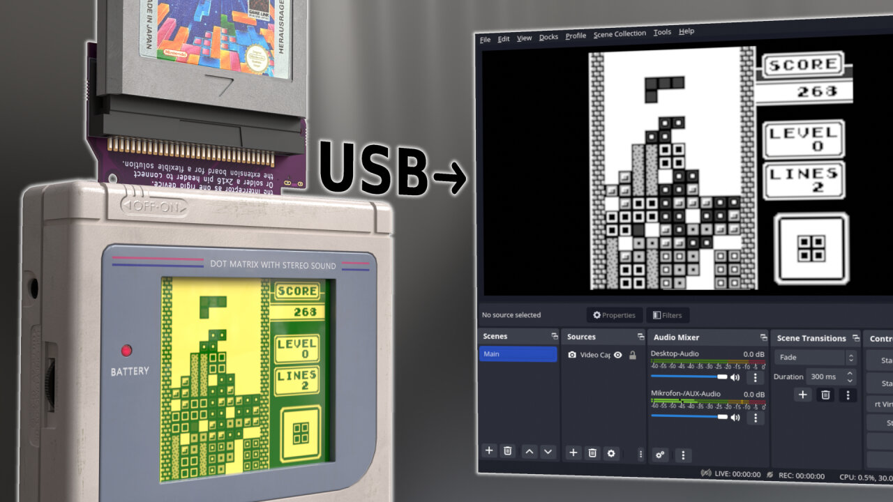
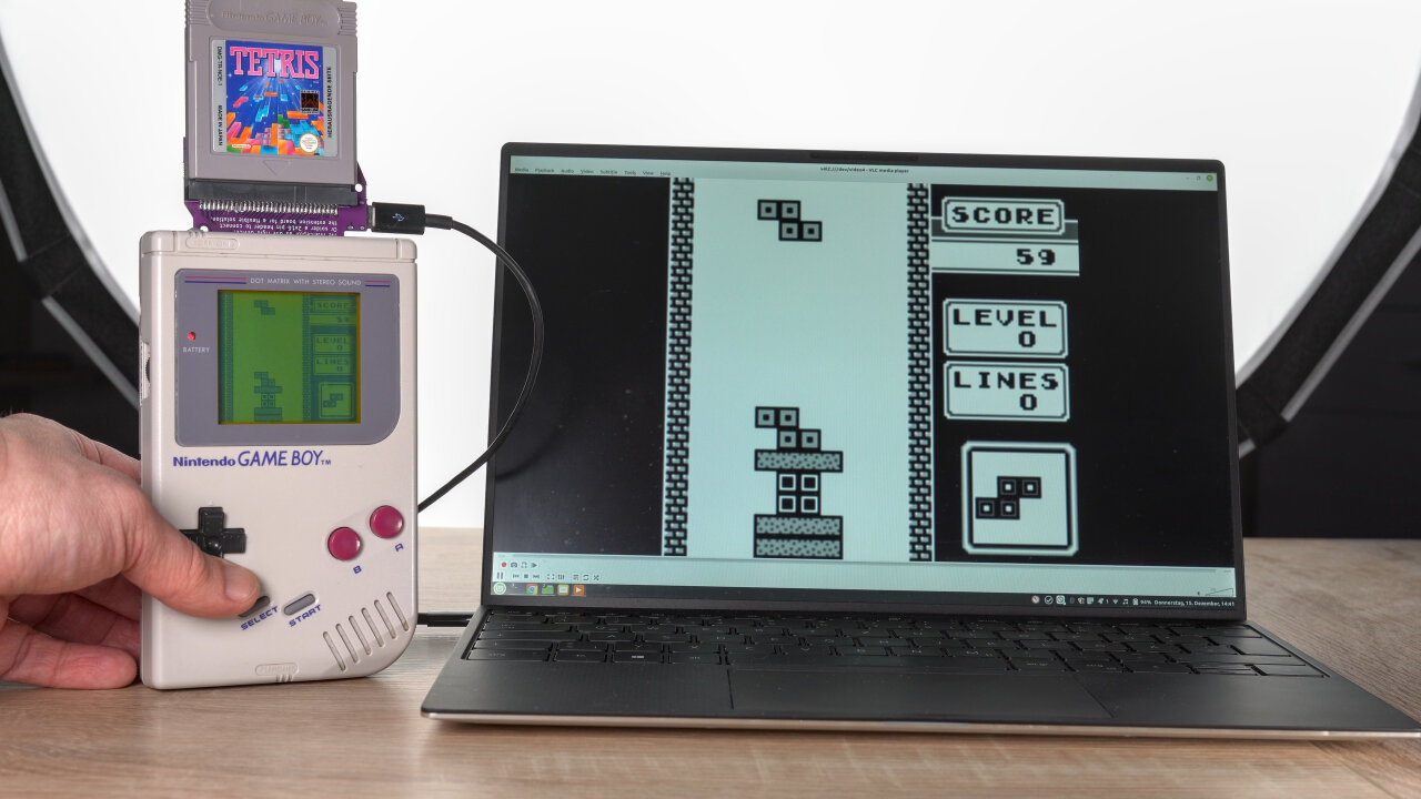
I present to you: The GB Interceptor. It is an adapter that goes between an unmodified Game Boy and the cartridge and offers a video stream of the game via USB.
The video above should give you a good overview of what it does, how it works and what its limitations are. This article here goes more into the technical details of how it works. If you are interested in how to order and build your own GB Interceptor, check out github and the order and build video.
The best way to explain why1 I developed and built the GB Interceptor is to explain which problem I tried to solve with it. A few months ago a Tetris enthusiast got in touch with me about this problem: An online Tetris tournament during which the contestants stream their gameplay.
Today, there is nothing unusual about streaming footage from a Game Boy. Emulators can easily do it and modern Game Boy variants like the Analogue Pocket offer HDMI output that could be captured. There also are some mods to add HDMI out to original Game Boy hardware, so getting a video stream from a Game Boy is a challenge that has long been solved.
The unusual detail about doing it for a Tetris tournament is that the players have to rely on their muscle memory which they trained on their personal Game Boys. Switching them for an unfamiliar modern device or an emulator will significantly impede their ability to play competitively. Also, you can imagine that a tournament that asks each contestant to first mod the hell out of their beloved Game Boys just to stream a video would not be well received.
So, we need a way to get a video from unmodified Game Boys also without modifying the game that is being played. Ideally in a form that can be used by anyone without complicated software or additional hardware like an HDMI grabber.
Well, in the end, the only connector with game data that is accessible on a Game Boy without a mod is the cartridge slot2. After all, the entire game data has to go through there. So, the idea is to create an adapter that connects the cartridge to the Game Boy directly and only adds the capability to intercept a copy of the transferred data.
However, this means that we cannot randomly access data of interest and we cannot see the data in RAM that the Game Boy’s CPU put together from the raw instructions from the cartridge. Especially, we cannot see the Video RAM, which would have been very nice as it would contain everything3 required to draw the image on screen. Instead, we need to create our own copy of VRAM.
To do so, I had to write an emulator to which I feed the data from the cartridge memory bus. For this I use an rp2040 (the Raspberry Pi Pico’s microcontroller) and split its cores to the two main processing parts of the Game Boy. One core emulates the CPU to recreate a copy of VRAM and the other core emulates the Game Boy’s graphics unit, the PPU4.
The CPU emulation actually is the trickiest part here, because it has to keep up with the memory bus that is pushing out events at a rate of about 1 MHz. If the PPU emulation falls behind, it would cause a short glitch like a flicker, but if the CPU emulation falls behind, it will eventually miss an event on the memory bus. Not only would the simulated copy of the RAM possibly get out of synch forever, but the emulator would not even be able to interpret the following instructions. An event on the bus is not always the next instruction, because the Game Boy’s CPU may take several cycles to execute some instructions while others are completed within a single cycle. So, the emulator has to keep track of how many cycles have to be ignored after a specific instruction before an event should be considered to be an instruction again. If we miss only one of them it becomes nearly impossible to get this right again.
This together with the overhead of emulating an 8-bit CPU on a 32-bit CPU made it necessary to overclock the rp2040 from its default 125 MHz5 to 225 MHz. The rp2040 can usually handle this without any problems, but still I would love to see if someone can improve the efficiency of my code to dial this back a bit.
Since the PPU emulation is not that critical and actually periodically gets some free time during the Game Boy’s vblank period when no image is being drawn, it also handles USB communication.
The actual hardware to implement this is pretty much a Raspberry Pi Pico with some bus transceivers to connect its GPIO ports to the cartridge bus. From the 32 pins of this bus, two are used for +5V and ground, one is used for analog audio6 and one is used to control the reset state of the Game Boy. The other 28 pins are connected to the rp2040, which therefore gets access to 16 address pins, 8 data pins and the four bus control pins clock, read, write and chip select. Since these use 5V logic I use the same bus transceivers that already served me well in the WiFi Game Boy cartridge to convert the signals to 3.3V for the rp2040.
This leaves two GPIOs unused. One observes the voltage on the +5V line to check if the Game Boy is turned on or not and the other one controls a status LED and reads a mode button.
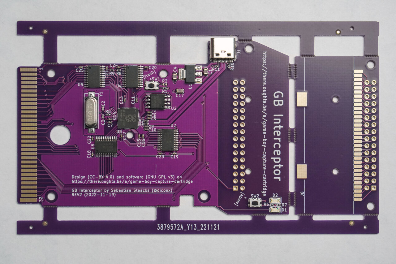
The rest of the cartridge is based on the minimal hardware design example for the rp2040 by the Raspberry Pi Foundation. This includes an oscillator, flash memory, a voltage converter and a USB port, which I replaced by a Type C variant.
That’s pretty much it. A Raspberry Pi Pico in Game Boy cartridge format hooked up to the Game Boy’s memory bus. The schematics and PCB designs can of course be found in the project’s github repository.
What really let’s the GB Interceptor do what it does is its software, which can of course also be found on github. In the following I will write about some of its details.
The GB Interceptor streams the resulting image using the USB video class implementation of TinyUSB, so in theory no drivers are needed and it should just show up as a webcam. Well, in theory. Unfortunately, this only works as expected on Linux, where I can directly use the GB Interceptor in VLC, OBS, Zoom or ffmpeg. On Windows and Android many apps seem to have trouble with the format of the video stream. On Windows, for example, VLC (despite working on Linux) complains that no suitable format could be found while OBS works perfectly fine without any settings or drivers required. On Windows this is good news because you can use OBS as a virtual webcam to forward the GB Interceptor stream to any software that is picky about the format. A list of tested host software can be found on github.
Unfortunately, at the time of this writing I was not able to get any video on MacOS and I am not yet sure why. For some reason it does not even trigger TinyUSB to enable the video stream, so I am not entirely convinced that it is the format. Keeping in mind that I have not yet done many tests on MacOS and that the video class implementation in TinyUSB is very recent and experimental, I hope that I can fix this in the future. Even if I could not get the video class to work here, it should be possible to pump the images through UART on the USB bus and use a simple Python script to convert it to a video stream on the system. You can check the current state of this issue on github.
So, what is that unusual format? Well, obviously, this starts with the Game Boy’s resolution of 160x144 pixels, which I can imagine might surprise some software expecting a modern 1080p stream. But it gets a bit more complicated when we look at the limitations that arise from the rp2040’s Full Speed USB port and its implications for the isochronous transfer implemented by TinyUSB. This combination means that the maximum buffer size for this endpoint is 1023 bytes and since isochronous transfer happens every 1 ms, we get 1,023,000 bytes per second.
If we just look at the raw image from the Game Boy, this is more than enough. The Game Boy has a “color depth” of 2 bit, so one image frame is 5760 byte. With roughly 60 frames per second we only require 345,600 bytes, which is why I see a custom UART protocol as an interesting alternative on MacOS if all else fails.
However, we do not want to need a driver or additional software. We want something that just works and unfortunately there is no 2bit color format that is widely accepted. Instead, there are plenty of compressed formats for which we do not have enough computation power left7 and some uncompressed color formats that are considered to be widely supported, most of which use 16bit per pixels. Instead we use a supposedly also widely supported slightly more efficient format: NV12 with 12 bit per pixel. The 12 bit are comprised of 8 bit per pixel for luma (grayscale brightness) and 16 bit shared by four pixels (hence 4 more bit per pixel) for the color information.
The good news is that the color data of the entire frame is stored at the end, so we can set it to gray or green once and can ignore it. In fact, we can treat the data before as a simple 160x144 pixel buffer with 8bit grayscale data, which is more or less ideal for our purpose.
The bad news, of course, is that it still takes up 6 times as much data as the original 2bit image would have needed. With our 1,023,000 bytes per second we are now limited to 29fps.
So, overall we have a 29fps NV12 stream at a resolution of 160x144. Not exactly what all those video conference tools expect.
By the way, although the GB Interceptor therefore only pushes out 29fps, it still works internally with 60fps and blends these frames to emulate the latency of the old LCDs. It just pushes out the latest blended frame whenever the USB bus calls for it.
Now after I explained how to get the result out from the GB Interceptor, let’s talk about the other end: How to get the communication on the cartridge bus to the rp2040.
Remember how much I struggled with my WiFi Game Boy cartridge when I tried to listen to a single event with an ESP8266? Interrupts were too slow8 and keeping the CPU in a tight loop observing the clock line was not an option. Well, the rp2040 has a trick up its sleeve: Programmable IOs. These are simple state machines that can directly access the GPIO pins as well as a FIFO buffer to/from the CPU. And these PIOs simply laugh at this task.
All we need to do is wait for the clock line to become low and then simultaneously read the remaining 27 GPIO pins that are connected to the Game Boy’s memory bus and write the result to the FIFO. For this we only need a single PIO and that executes only four instructions:
1
2
3
4
    wait 1 pin 28 ;Wait for CLK to go high
    wait 0 pin 28 ;Wait for falling flank of CLK
    mov isr pins  ;Read all GPIO pins to the input shift register
    push          ;Push the ISR to the FIFO
From there, the CPU can just pick up one of these events packed into a single 32 bit integer from the FIFO whenever it is convenient.
Now it is time to talk about what these events look like. Or rather, how we need to deal with them. At this point I expect that you have a basic idea of how the Game Boy works. For those who are not familiar with Game Boy development I always recommend Michael Steil’s “Ultimate Game Boy Talk”.
As explained above, the basic idea is that one core of the rp2040 interprets the incoming bus events such that it follows the same instructions as the Game Boy’s CPU. That is, it emulates the Game Boy CPU in order to recreate an exact copy of VRAM (and OAM). The second core then acts as the PPU and renders an image from our VRAM copy. This is mostly just the implementation of a basic Game Boy emulator, but there are some differences that I would like to talk (or write) about.
First of all, there are several things that become much simpler in this scenario. Think about the program counter and conditional jumps. We do not have to implement those. The real Game Boy fetches the next instruction anyways. It does not matter if it is the next instruction by incrementing the PC or if it jumps to an entirely different address. The real Game Boy will fetch the next instruction and we do not have to care about where the instruction came from.
This solves one of the seemingly biggest issues: We cannot see any of the hardware I/O registers. In particular, we do not see the input from the game pad! How should we ever emulate a game if we cannot see the player’s input? Well, almost every code in existence will compare the gamepad input to check which button was pressed and make a conditional jump to code that is triggered by the button. Our emulator will simply follow these same instructions and does not have to care whether it was triggered by a button press.
You could say that the GB Interceptor is an emulator on rails.9
This only becomes a problem if the data from the I/O registers eventually ends up in VRAM. Imagine that the value of the gamepad is added to a base address to calculate the tile index to an image that shows the current state of the D-Pad. The CPU would get the instruction to fetch the gamepad register value, add a number to it and our emulator would not know the correct result of that operation. This result is then written to VRAM and we have no idea what is in that location.
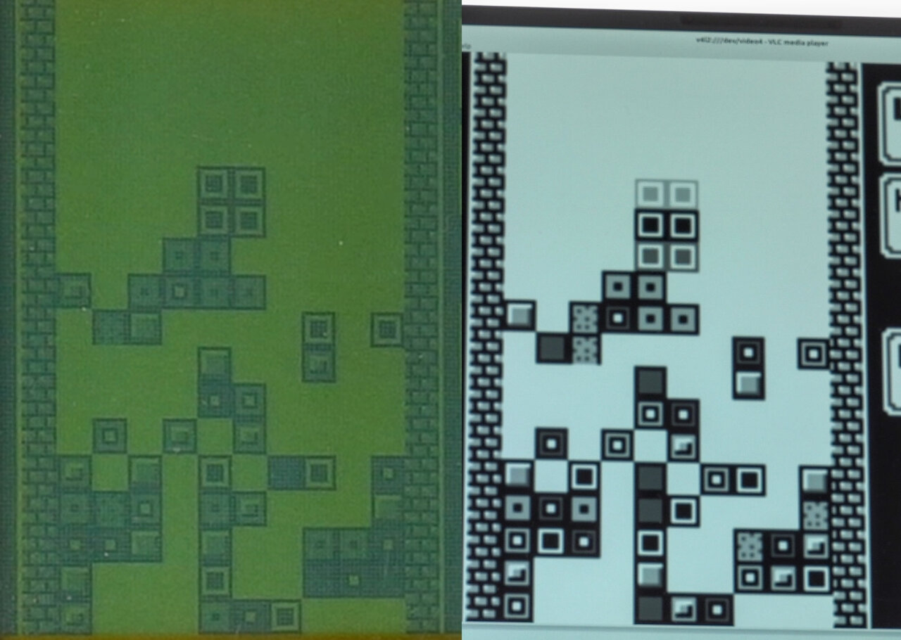
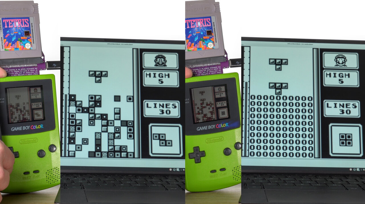
However, these should only amount for small visual differences. I do not know of any example where this is done with the gamepad I/O, but I have an example for the DIV register. In Tetris it is used as a source for random numbers and most of the time it branches the code through conditional jumps to pick different blocks that come next or to generate the initial pile of garbage blocks in game mode B. We do not see that random number, but when it triggers the code to logically pick the upcoming block, we will still get the same block as we get to execute the same code. This also goes for the decision whether a block of the garbage pile in mode B is empty or filled, so we also get the same layout for the garbage stack. But those garbage blocks also have a randomized visual style and that is not based on branching code, but just a random number added to a base tile index.
The result is that we see the same garbage stack layout on the GB Interceptor, but the individual blocks have a different look. This is harmless and you would only ever notice if you compare the image to the Game Boys screen.
We only get into real trouble when an entire stream of prepared data is written to VRAM from one of the I/O registers. The only example that I know of (and that I can think of) is the link cable. Here, we can look at the same example of the mode B garbage stack, but in two player mode of Tetris. The problem is that both players should have the same garbage stack. So, the Game Boy that starts the game first will generate that stack and send it to the second one via link cable. The second one writes the data directly to VRAM without any checks or conditional jumps and we cannot see anything.
Therefore, in two player Tetris, the GB Interceptor works fine if it is in the Game Boy that starts the game first (except for the different visual style of individual blocks), but it produces unusable output if it is in the second Game Boy.
Speaking of the DIV register, this is actually an I/O register that we might be able to emulate. Since we get the exact clock from the Game Boy we can count an emulated register in synch with the real one without any danger to diverge. There are only two problems:
The thing is that we actually measure how many rp2040 clock cycles occur for each Game Boy clock cycle during the boot sequence before the actual game starts. Here we can observe thousands of cycles and should be able to get a very precise substitute clock from our rp2040. Unfortunately, for performance reasons, I only use an integer ratio of both clocks, which typically is in the order of 225 rp2040 clocks per Game Boy clock. This means that just the rounding error will lead to an error of roughtly one cycle per 100 cycles during a halt state, which happens regularly.
So, maybe we can do a fractional clock count, but for now as it only affects the div register which I cannot properly initialize anyway, this is not implemented.
While we are on the subject of synchronizing our emulator to the real Game Boy… We of course also need to synchronize our PPU to the one of the real Game Boy. Otherwise any effect that requires changes in the VRAM midframe would lead to glitches and at least we would see some tearing effects as data is updated in VRAM randomly.
The problem is, that no trace of the PPU can be found on the memory bus. We have to deduce the state of the PPU by the behavior of the game, which has to synch to the PPU as well - at least to know when it may write to VRAM. The big problem here is that games can use many different ways to do so.
The most common method, is the vsync interrupt. Most games simply let the Game Boy trigger an interrupt when vsync is reached and we can see when the code of this interrupt is being executed, so we can simply adjust the timing of our own emulated PPU to enter vsync at that same moment.
Unfortunately, there are many other options to do this. Another common one for games that need to squeeze out a bit more access to VRAM (for example implemented in Donkey Kong Land) is to read the LY register in a tight loop and to periodically compare it to a specific line number. A conditional jump jumps back to the LY readout until the correct line is reached and the code simply goes beyond the conditional jump. Luckily, the developer can save a few cycles by jumping while it is not reached, so many games do it this way, which allows for a simple and naive detection of these tight loops in the Interceptor.
However, there will be games out there with a different approach (like my Wifi cartridge) and the output of the GB Interceptor will look glitchy until a detection for these other methods has been implemented.
Oh, and while interrupts are a blessing to synch the PPU, these are not exactly easy to detect in the first place. We need to keep track of every single instruction and how many cycle the Game Boy needs for each instruction to be sure which event on the memory bus would be the next instruction. The Game Boy jumping to a different point in the execution and taking a few extra cycles to do so is not exactly helpful here.
Have a look at the first vsync interrupt of “The Legend of Zelda - Link’s Awakening”10 on the original Game Boy:
1
2
3
4
5
6
7
8
9
10
11
12
13
14
15
  Address Data Instruction
   01a2    fb    EI
   01a3    c3    JP a16
   01a4    bd
   01a5    03
   81a5    71
   03bd    3e    IRQ
   82bd    01
   82bd    01
   dffe    81
   dffd    a5
   0040    c3    JP a16
   0041    25
   0042    05
   8042    24
When ignoring interrupts, we would falsely interpret 0x3e in line 7 as an opcode. The only way to be more or less sure that we are seeing an interrupt is by implementing the GB Interceptor such that it reads ahead11 a few cycles to recognize an interrupt before the current event is misinterpreted as an instruction when in truth it is just garbage on the memory bus while the CPU takes a moment to enter the interrupt.
Luckily, the Game Boy jumps to few fixed addresses during an interrupt, so we look out for those. But since these addresses could theoretically also be called from regular code, we mix in a few more indicators, specifically the behavior of the stack pointer. During an interrupt call, the current PC is pushed onto the stack, so the SP register is decremented twice and the Game Boy writes to the two decremented addresses. Usually these do not point to an address belonging to the cartridge, but these addresses are still visible on the memory bus, so this adds to our confidence to detect an interrupt.
The only trouble with this is that the Game Boy is not really required to do this consistently and to show the SP address on the memory bus as no game cartridge cares about these operations. Therefore, it is not surprising that we can see a few differences here between different devices. Here is only the interrupt call for the original Game Boy (DMG), the Game Boy Color and the Analogue Pocket:
1
2
3
4
5
6
7
8
      DMG                 GBC                Pocket
  Address Data        Address Data        Address Data
   03bd    3e          03bd    3e          03bd    3e
   82bd    01          83be    00          dfff    00
   82bd    01          dfff    00          dffe    01
   dffe    81          dffe    80          dffd    9b
   dffd    a5          dffd    00          0040    c3
   0040    c3          0040    c3          0040    c3    <   Next instruction
If we look at this closely, we find some slight differences: The DMG also shows the SP address before decrementing it, the GBC only shows the two decremented addresses it actually writes to and the Pocket does this one cycle earlier. Taking all these cases into account, of course makes our interrupt detection less reliable and at the moment it does not work properly with the variant of the Pocket.
I think these are the most interesting parts of the implementation. Kudos to you, if you have read up to this point - you are a true 8bit geek!
If you want to see even more details, you now have to dive into the code on github where you can also find the hardware design files and material for cases. I hope that there will be some community contributions to both, the code and hardware design, so if a few months have passed since the publication of this article, this is also something that will mostly take place on github.
If you want to build your own GB Interceptor, you should also watch the order and build video.
I hope you enjoyed this project!
This project would not exist without the work by many people who researched, tested and prodded the Game Boy before me and (most importantly and why I am writing these articles myself) documented their work. Here are some of my most important resources:
To be honest, my personal motivation was that I immensely enjoyed the challenge. The Game Boy just has the right amount of complexity to pose a challenge while still being simple enough to allow for an understanding of the whole system. ↩
One could argue that the link cable offers some data. But its bandwidth on a classical Game Boy is poor and it only provides some handpicked data if the game was programmed to send some data via link cable. Since we don’t want to modify the games, there is not much of interest on that port. ↩
Ok, you also need the OAM, but the concept is the same. ↩
Pixel processing unit or picture processing unit - depending on whom you ask. ↩
Some sources will say 133 MHz, for which the rp2040 is rated. I am referring to the reference implementation of the Raspberry Pi Pico and the Raspberry Pi Foundation’s minimal hardware example, which run at 125 MHz. ↩
The GB Interceptor does not implement audio at all, which can easily be captured from the headphone jack. ↩
I tried an mjpeg compression, but my implementation was way too slow to generate the frames just during the spare time during vblank. Maybe someone with more optimization experience or some additional hardware can help here in the future. ↩
To be fair, those were Arduino interrupts with their typical overhead. ↩
Yes, I use that phrase a lot. I like it. Wondering if the media will pick it up :) ↩
Opps, I mislabeled this as “A Link to the Past” in the video twice, didn’t I? ↩
Ahead is a question of perspective. Ahead from the point of view of the instruction that is currently emulated. Of course this means that the Interceptor lags behind a few cycles compared to the real Game Boy - but we are talking about microseconds here. ↩