
03 November 2023
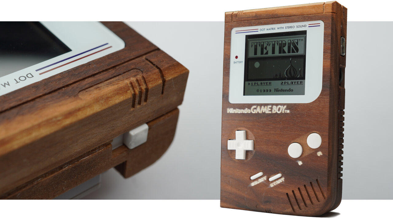
You made me create a wooden Game Boy shell. Yes, you made me do it. After I got myself a CNC machine a while back I just made a wooden Game Boy cartridge to get to know the machine, but social media wanted more. So, I made a Game Boy out of walnut wood.
You can see the process in the video without much explanation. If you want to learn about the toolpaths, my reasoning behind a few things, lessons learned and what you should avoid if you try this yourself, read this blog post instead and check out my design files on GitHub.
Please note that this article contains affiliate links, i.e. links that tell the target site that I sent you there and that earn me a share of their revenue in return, i.e. as an Amazon Associate I earn from qualifying purchases. In contrast to regular external links, such affiliate links are marked with a dollar sign instead of a box.
This project mostly began as a user request. When I got myself a CNC router a few months ago, one of the little exercises I did was a wooden Game Boy cartridge (see Youtube short clip or project files on GitHub). It was a mix of “let’s see if I can do that” and “sure the retro gamers on social media will love this”, but I did not expect how much they would love it and of course they asked for more. So, I did some testing, spent some time and several weeks later I find myself in the possession of a Game Boy with a beautiful walnut wood shell.
I mean, look at that thing. Isn’t it gorgeous? So, if you want to learn how exactly it was built, read on. If you just want to see some CNC timelapses and detail shots of the wooden Game Boy, you should probably watch the Youtube video instead.
Before we go into details, there are some general things you should know to properly judge the results. At least if you plan to reproduce the Game Boy, you should read these carefully.
Let’s start with the bad news for most of those who already have a CNC machine and just want to reproduce my work: I use the Blender CAM plugin. Yes, there is a CNC CAM plugin for Blender and it is free. Yes, it is quite versatile and powerful. Yes, using it is a pain in the ass even if you are used to Blender.
Still, I love it and the CAM alternatives that seem to allow me to do similar things are very expensive1. So, I ended up using Blender CAM, which unfortunately means that many CNC users out there will cry before having to copy my models to their CAM to painstakingly recreate the toolpaths there.
Therefore, the project files are blend files on GitHub and I release everything under the Creative Commons Attribution 4.0 license. Do what ever you like with it, just make sure to mention me as the source. …and maybe keep in mind that Nintendo might want to have a word about trademarks if you try to sell these with their logo on it.
In addition to the blend files I have also uploaded the gcode files that I actually used. They are for grbl-based machines, but even if your CNC uses a grbl controller it is a bad idea to just feed them to your machine. You will have to adapt it to the equipment that you actually use and I only added them as reference to review and compare.
Speaking of equipment-specific things: The feeds and cutting depths set in the blend files are for the weak spindle on my machine. If your spindle is stronger, you can quite certainly go a lot faster. But also keep in mind that the speeds in the blend files do not have any meaning. My spindle is not digitally controlled and since it has little torque at lower speeds I pretty much used it at its maximum of 10,000 rpm. You will have to adapt this to your machine and your bits.
Remember that I only got my CNC machine a few months ago, so do not expect comparative insights here. I will document what I use and try to explain a few things to people who have never used a CNC before. If you have a CNC and are just interested in the toolpaths, you can probably skip to the table with bits I used.
If you have never looked at CNC machines before, this probably looks like a very fancy and professional setup. If you know about CNC machines, you probably recognize immediately that it isn’t. My machine is a Genmitsu PROVerXL 4030 V2, which is the toughest Genmitsu CNC router, but in the world of hobbyist CNC machines ranks somewhere in the middle. It is much more rigid than the small 3D printer like machines (that Genmitsu machines are often associated with), but much smaller and weaker than machines by more prestigious brands.
As a beginner I think that it is extremely capable for my needs, but its weak spot is its stock 400W spindle. Compared to stronger machines you will find that my toolpaths take much longer as I am doing significantly shallower cuts. Also the spindle is pretty much limited to its top speed of 10,000rpm as it seems to lack torque at lower settings. For the finer tools I would have wished for a higher speed and for some situations a reduced speed might have been beneficial as well. Luckily, this can be upgraded and I probably will do so in the future.
In the end, I mostly chose the 4030 V2 because of its rather small footprint. While others might consider this to be a disadvantage, it was the largest machine that I could fit into an enclosure onto my workbench. Since I do not have a proper wood workshop, the machine has to share a room with other hobbies in my basement, which means that I needed to address noise and dust, because CNC machines can deliver plenty of both.
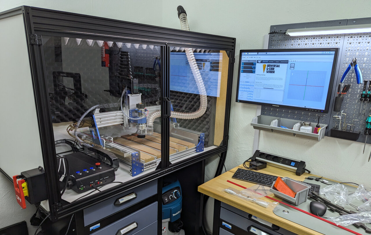
I went for the OpenBuilds Enclosure Kit 510, added acoustic foam and paired it with the Genmitsuo dust shoe and a flexible hose. The vacuum hose then runs through a cyclonic separator and ends in a Makita vacuum. Add a workbench, an LED lamp inside the enclosure and a screen at the side (you might recognize this one from my bullet time rig) and that’s my setup.
Just a few warnings if you are thinking about picking up CNC as a hobby: Do not underestimate the noise and the amount of dust such a machine produces. The enclosure and dust extraction in my case ate up a huge part of my budget for a good reason. If you are in a dirty workshop far from other people you can ignore the enclosure, but please still think about your hearing and your lungs. I highly recommend to use a dust extraction system anyway and if you are doing this in a room that you spend a lot of time in or that you use for other things in general, a simple shop vacuum will not be enough. Fine saw dust will escape regular vacuums and you should really look into ones with a filter for dust class M.
Oh, and one more warning: I do not have a problem to leave my 3D printer unattended as long as I can check in once in a while through a webcam. The typical 3D printer accidents turn the machine into a PLA spaghetti factory, but it is still ok if you stop it 15 minutes later. The more dangerous typical fail state of a 3D printer is a cable fire especially on cheap printers like mine, but if you place your printer in an environment of low flammability there is plenty of time to recognize the problem before severe consequences.
This is different for a CNC machine! If things go south with a CNC machine, they go south fast! The typical CNC accident means driving a sharp piece of metal rotating at 10,000 rpm into something that was not supposed to receive that piece of metal. You can break a lot of stuff within seconds and that is the harmless case. Imagine running that 10,000 rpm metal stick into a dry piece of wood and leaving it there because of a failure or maybe because that wood got loose and now follows your machine. Remember those adventure movies where they make fire with a rotating stick? Do this with a 400W motor covered by saw dust and maybe with a dust extraction system sucking everything into the big container with even more sawdust.
The point is that you should not leave a running CNC machine, have a fire extinguisher nearby and make sure to have an easily accessible emergency stop that actually cuts power to your machine (in case of an enclose, put something like this on the outside). Here is a video to encourage you to take this serious.
Like in the previous section, I will be talking to people new to CNC routers here. Someone who already knows this stuff will probably just have a glimpse at the table below anyway.
While CNC machining often looks like you are just pushing a common drill bit to some wood, this is not what is happening at all (unless maybe you are actually drilling holes with your CNC). What looks like a drill bit usually is a milling bit (a so-called end mill). It is not designed to plunge vertically into the material (although in many cases it has to be able to do this, too), but to carve away material horizontally.
One interesting aspect of this is that the spiral of the bit might go in different directions. Some bits have a right-handed spiral like a drilling bit, but others can be left-handed or not even have a spiral form at all. The reason is that the actual milling is done at the side and just requires sharp edges while the spiral mostly helps to move the material away from the cutting edge. Right-handed drills are common as you want to push material upwards out of the drilling hole and for the same reason you will find many end mills with that shape. They pull material upwards and away from your work piece, therefore they are called “upcut” bits. The downside of this is that the upwards motion can fray the edges of your work piece, which is why I also often use the counterpart with a left-handed spiral, the “downcut” bit. There are also some other forms and compromises, but I only have those two variants and so for each task I have to pick a suitable diameter for my end mill (obviously you need small ones for details and large one to remove much material fast) and decide between upcut and downcut as a trade-off between a nice finish and efficient material removal especially in tight spots.
Another aspect is the shape of the tip of the bit. The most common one is the flat end mill, which is best suited to create a flat surface. However, if you want to create a curved 3D shape, this is not a good choice as it tends to create little steps that look similar to the layers of 3D printers. A ballnose bit with a circular tip can help as it can create a slope between one line to the next one.
A very important shape is the V-shape. On one hand, this is used to directly create angled edges (chamfers) in a single pass, but also they can be used to carve text or other designs. Imagine to just try and cut a small square. If you use a flat end mill with a 3mm diameter, you can quickly remove the material from the square, but the corners will always be rounded with a radius of 1.5mm. So, instead you use a smaller end mill, let’s say 1mm. Now it takes ages to remove the material2 and still have round corners, now with a radius of 0.5mm (which might be ok for many use cases). That’s where the V-bit shines: If you do not care about how deep you cut, but just want to have a 2D shape at the surface, a V-shaped bit can simply use different depths to have different diameters at the surface. Need a tiny bit for a sharp corner? Only use the very tip of the bit. Need a large diameter to clear most of that example square? Go deep for a large radius. The result is a typical angled V-carving look that many (including me) find quite pleasing. Just search for V-carving on Youtube to find a bunch of very satisfying videos.
Unfortunately, that still is not all that needs to be considered when picking the right tool for each detail. You also need to consider the cutting length and the overall clearance of your bits. The cutting length is how deep the bit can go so that its sharp bits are still cutting away material instead of its dull bits just rubbing the wood and heating it up. That’s not much of an issue for me as my weak spindle usually limits the depth of my cuts anyway. The clearance is a much bigger issue because overlooking it usually causes some kind of damage. Whenever you cut into the material (or when you use clamps to hold your stock3) you need to have enough space for your machine and the rest of the bit. The machine itself mostly becomes a problem for deep pockets, but those small diameter end mills often still have a larger shaft. So, even if you observe the cutting length, you cannot cut at the side of a straight wall if you would run the shaft of your bit into it.
That should be enough of an overview. I am mostly writing down what I learned from others (mostly Youtube) over a few months, so I would recommend that, too, if you want to go deeper.
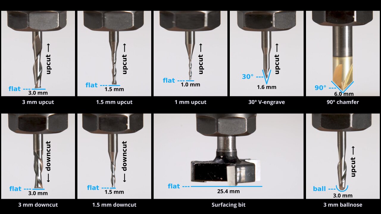
Now, finally, here is the list of bits I used in this project and the short name I use for them henceforth4.
| Label | Diameter | Shape | Direction | Exact product |
|---|---|---|---|---|
| 3mm upcut | 3.0 mm | flat | upcut | Sorotec L2SF.M.0300 |
| 1.5mm upcut | 1.5 mm | flat | upcut | Sorotec L2SF.M.0150 |
| 1mm upcut | 1.0 mm | flat | upcut | Sorotec L2SF.M.0100 |
| 3mm downcut | 3.0 mm | flat | downcut | Sorotec L2SF.0300.LI |
| 1.5mm downcut | 1.5 mm | flat | downcut | Sorotec L2SF.0150.LI |
| 3mm ballnose | 3.0 mm | ballnose | upcut | Sorotec FR2612.0300.24 |
| 30° V-engrave | 1.6 mm | 30° V-shaped | upcut | Sorotec LGS.0030 |
| 90° chamfer | 6.0 mm | 90° V-shaped | none | Speed Tiger 90° |
| Surfacing bit | 25.4 mm | flat / surfacing | none | Baorder JYH0075 |
Please keep in mind that I only got my first CNC router a few months ago, so these are mostly the first bits I ever used. I have no comparison to tell if they are good or bad, so take this as pure documentation and not as an endorsement.
Ok, it’s time to get serious. In the following I will go through all the toolpaths one by one and try to remember details that you should know about. For each one I will mention the bit I used, how long it took and the name of the gcode file I used (if available). As mentioned above it is unlikely that you can use the gcode file directly, but you should be able to view it in order to understand what the toolpath does.
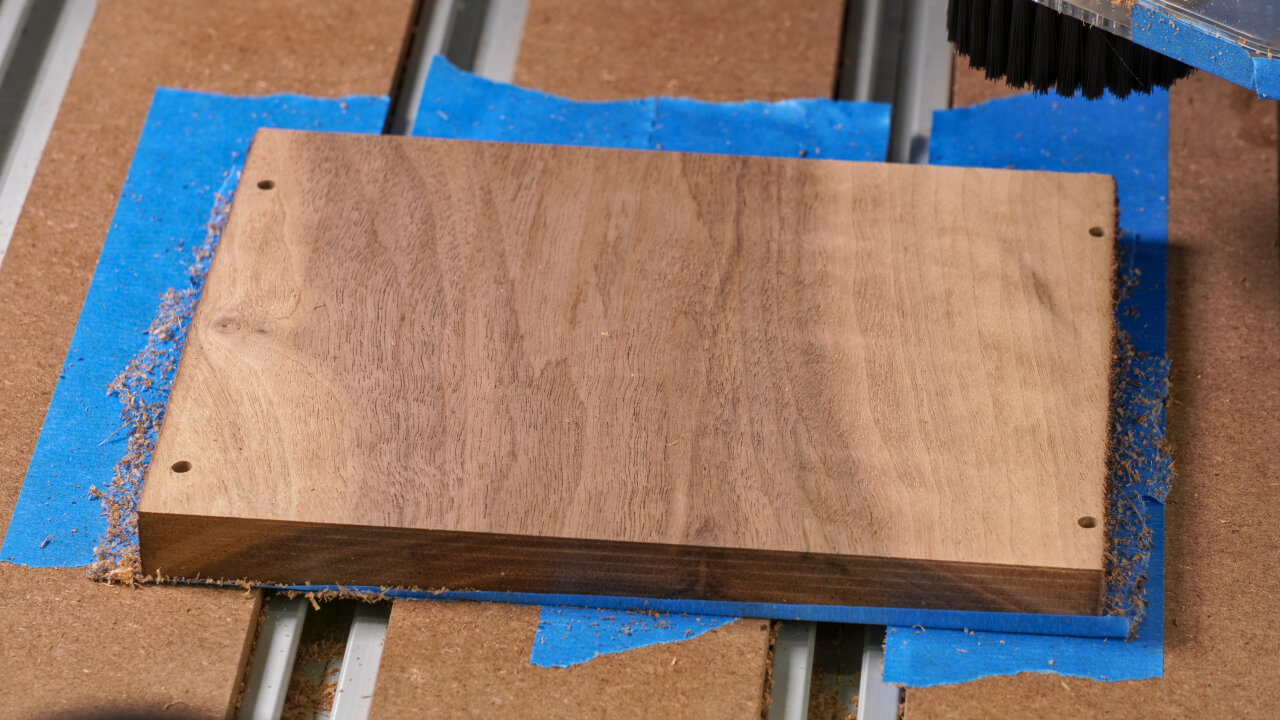
The first step is to create the outside of the bottom half of the shell. For this you need a piece of wood with at least 160mm by 99.6mm and it should have a thickness of at least 23mm. Having a few more millimeters is highly recommended to allow for a few surfacing steps without becoming too thin.
| Purpose | Tool | Gcode | Duration |
|---|---|---|---|
| Surfacing | Surfacing bit | N/A | 17 min |
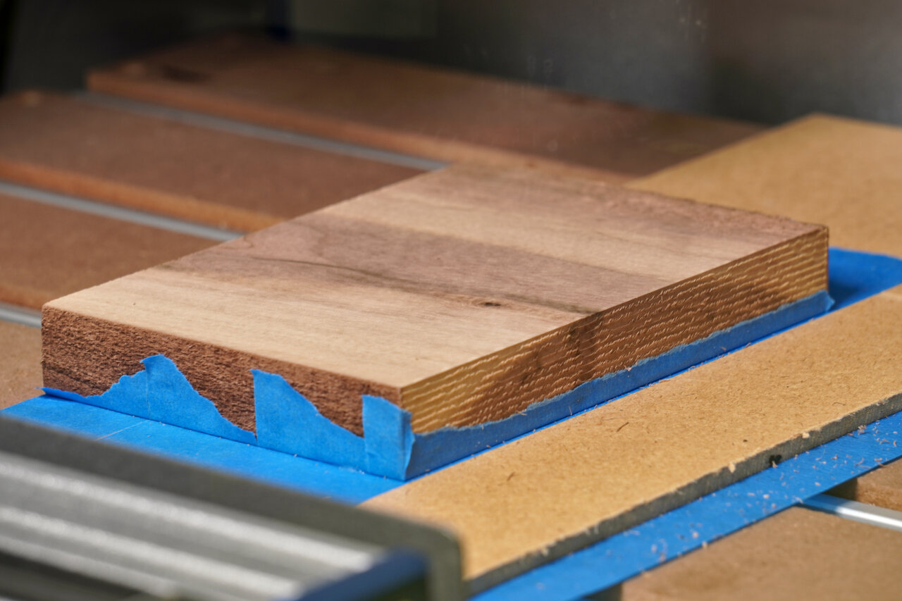
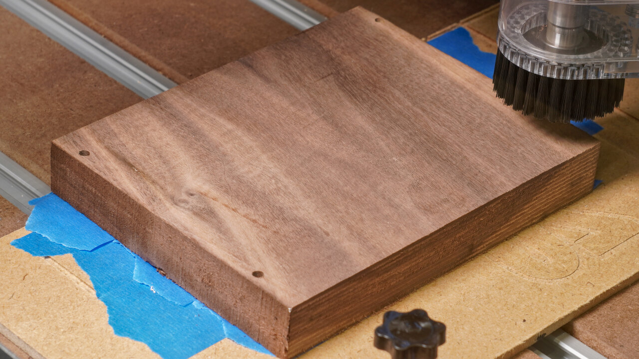
And surfacing is exactly what we start with. The current surface will be the one visible on the back of the Game Boy shell. So, it should look nice and needs to be surfaced down to a clean even plane. Keep in mind that the remaining thickness needs to be at least 23mm even after possibly surfacing the other side too. The exact thickness does not matter yet, so just aim for a nice finish on this side.
| Purpose | Tool | Gcode | Duration |
|---|---|---|---|
| Hole to allow deep dive of 1mm bit | 3mm upcut | 1-reference-frame-pockets-3mm-flat-UPCUT.gcode | 5 min |
| Reference for flipping | 1mm upcut | 2-reference-frame-drill-1mm-flat-UPCUT.gcode | 4 min |
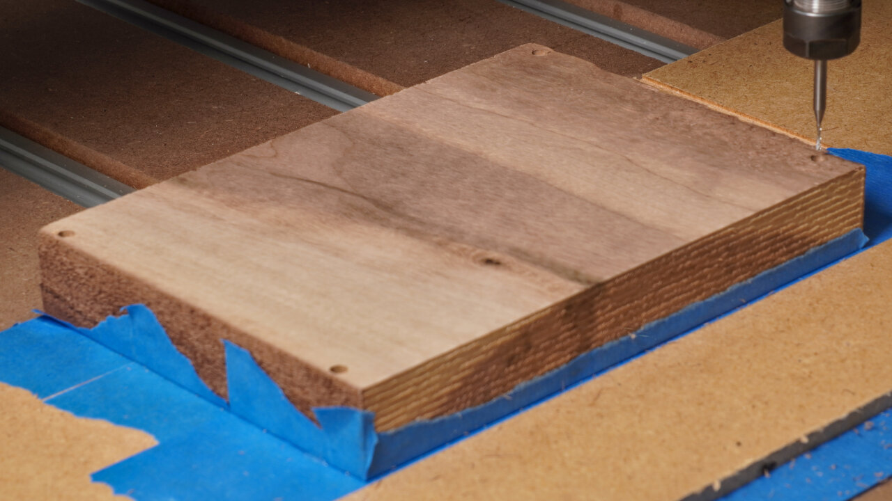
This is my method of aligning the workpiece after flipping it. I drill small holes through to the backside that I can use to align it after turning it around. If you have a better way of doing this like a flip jig, a tool to measure distances along all three axes or even an additional axis, you can skip this toolpath.
I labeled this as a single path, but please notice that I have split it into two gcode files. The reason is that the working distance of my smallest bit is too short to go all the way through 23mm without hitting the wood with its wider 3mm shaft. So, there is a first step of drilling space for that shaft before creating the smaller and more precise holes on the backside.
If you use my solution, take note that zero is set to the corner of the Game Boy, so the hole in that corner will be drilled 5mm along negative x and y. So, when picking the start point to fit the 160mm by 99.6mm of the reference frame, keep in mind to offset zero by 5mm in both directions. This will be the zero for all subsequent steps, too.
Oh, and obviously, this step will drill through the entire workpiece and into your spoilboard.
| Purpose | Tool | Gcode | Duration |
|---|---|---|---|
| Profile cut | 3mm downcut | 001-bottom-outside-1-profile-3.0mm-flat.gcode | 15 min |
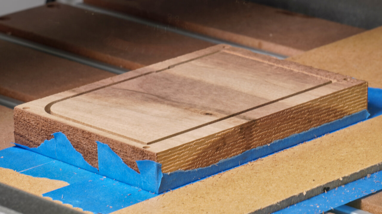
Next I do a profile cut that does not go all the way through. It will eventually meet with a profile cut from the other side (if aligned properly). At this point it also gives room for a few upcoming toolpaths that enter and leave the outer rim of the Game Boy shell.
| Purpose | Tool | Gcode | Duration |
|---|---|---|---|
| Curved sides of the back | 3mm ballnose | 001-bottom-outside-2-3d-3mm-ball.gcode | 63 min |
The curved sides on the back are created with a ballnose bit. However, I can still see distinct lines from the tool passes, so if you want to avoid that you need to set a higher overlap between passes or you need to do a better sanding5 job than me.
| Purpose | Tool | Gcode | Duration |
|---|---|---|---|
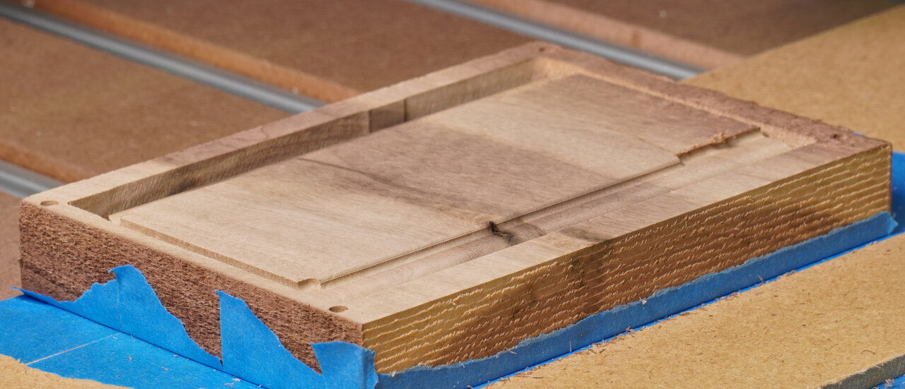
| Pocketing of cartridge slot and battery compartment | 3mm downcut | 001-bottom-outside-3-pocket-3mm-flat.gcode | 84 min |
This step carves the pockets for the cartridge slot and the battery compartment. Note, that it removes more material in the battery compartment than on the actual original Game Boy shell to make space for the upcoming toolpath using a 1.5mm downcut bit. My 1.5mm bit only has about 8mm of clearance before sloping into a 3mm shaft, so in order to create the finer details inside the battery compartment some room needs to be made. If you have a bit without such a limitation, you might want to optimize this towards the original.
| Purpose | Tool | Gcode | Duration |
|---|---|---|---|
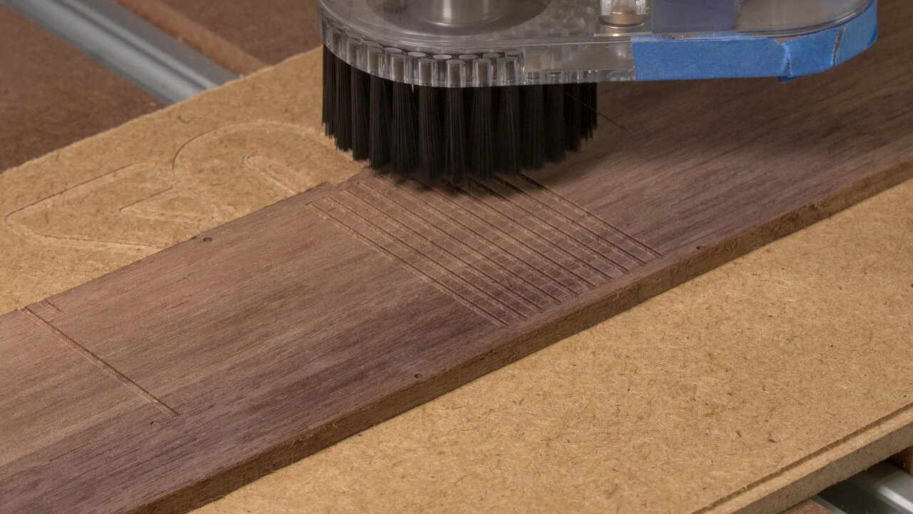
| Details of battery compartment and lines on backside | 1.5mm downcut | 001-bottom-outside-4-details-1.5mm-downcut.gcode | 40 min |
As mentioned before, this adds some details in the battery compartment. Important ones: These are the slits that will hold the battery contacts. My design is made for some after market contacts (see assembly section), but it has too much room and I needed to put something behind the contacts to hold them in place. If you know the exact contacts you want to use, this is something that could be optimized.
Oh, and this path also creates the decorative lines on the back of the Game Boy.
| Purpose | Tool | Gcode | Duration |
|---|---|---|---|
| Drilling screw holes | 1.5mm upcut | 001-bottom-outside-5-holes-1.5mm-upcut.gcode | 3 min |
The last step on this side drills some holes for the screws. These are not the holes the screws tap into, but the holes that the screws go through first. I have not tested the diameter much because I ended up gluing the shell, but they seemed ok.
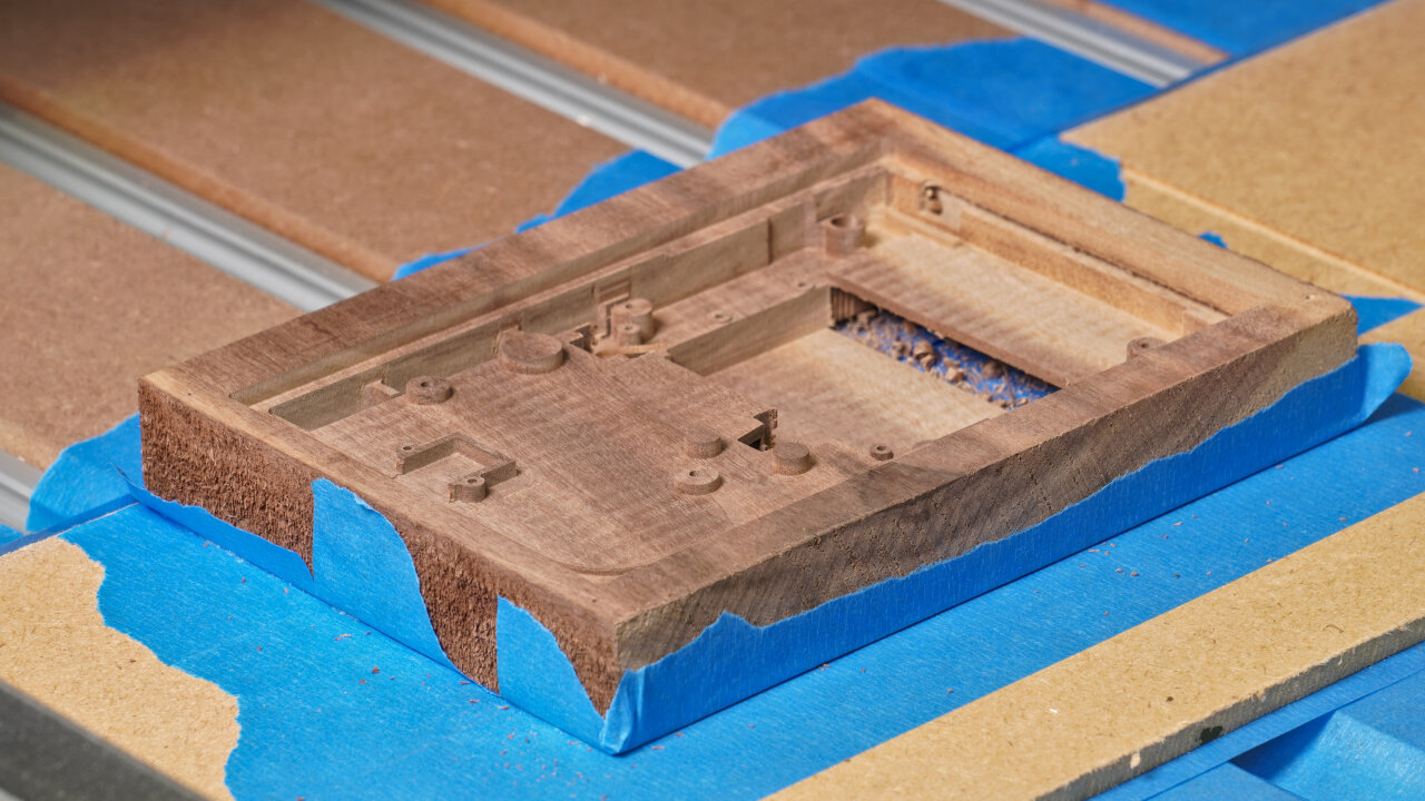
Now it is time to flip the workpiece to do the inside of the bottom half. To do so, align it with your favorite method.
If you use my reference drills, align your workpiece such that you can jog 160mm along x and 99.6mm along y and always end up on one of the small 1mm holes as precisely as possible. Remember that you cannot fix the rotation of your workpiece if you use the tape and glue method (like I do), in which case I would recommend using a carpenter’s square to get the orientation right while gluing it and then use the holes to verify and to set zero.
Speaking of zero on my reference frame: Remember that the hole is at -5mm and -5mm, so align your bit above the correct hole and then move it by 5mm along x and y before setting zero. Keep that zero for the rest of the steps for the bottom half.
| Purpose | Tool | Gcode | Duration |
|---|---|---|---|
| Surfacing | Surfacing bit | N/A | depends on original thickness |
Once again, it is time for surfacing. However, this time you are aiming for a final thickness of exactly 23mm. Of course, if you need to remove a lot of material, you can use a different method first, but at the end of this step you should have a perfectly flat workpiece with a thickness of 23mm. I designed the two sides to allow for a little uncertainty here, but I would say that you should hit 23mm to within about half a millimeter.
| Purpose | Tool | Gcode | Duration |
|---|---|---|---|
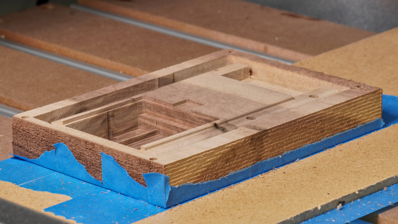
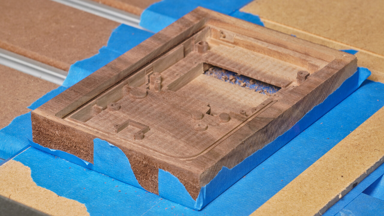
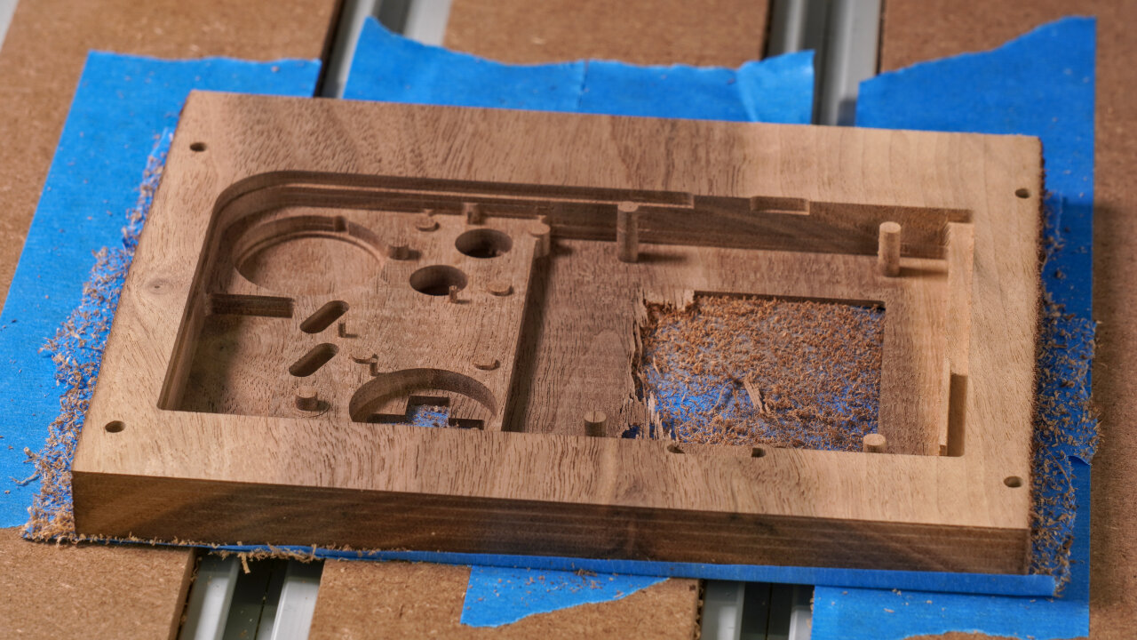
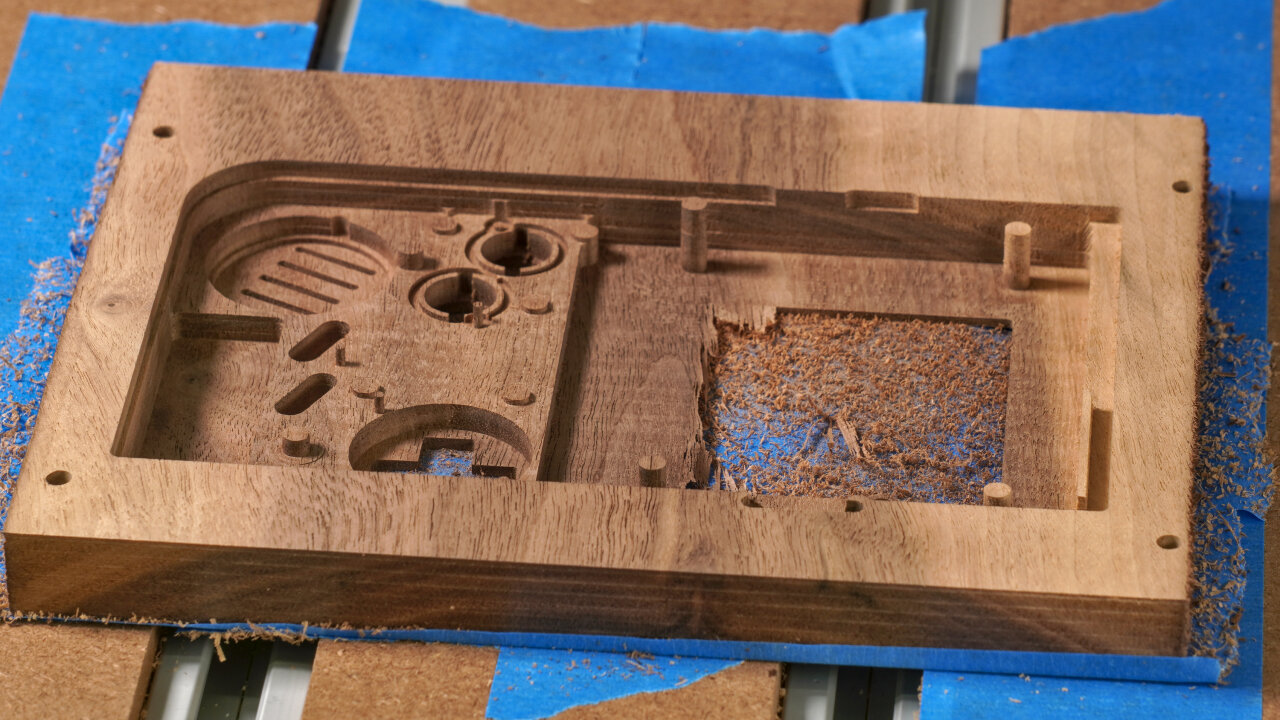
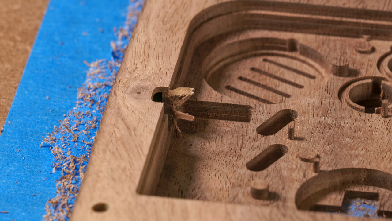
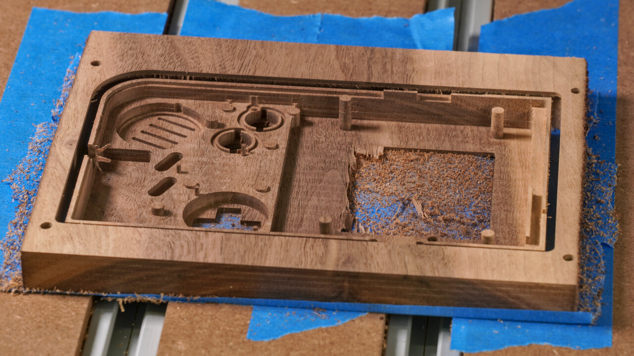
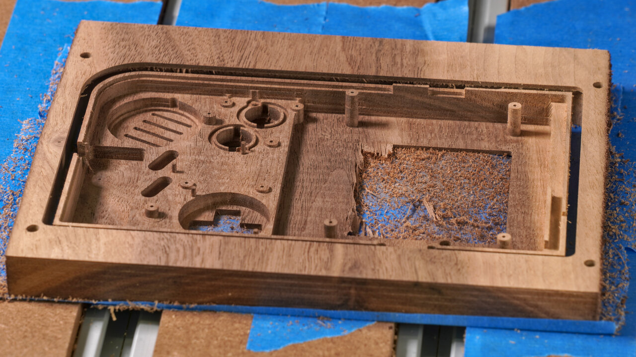
| Pocketing of most internal geometry | 3mm downcut | 002-bottom-inside-1-pocket.gcode | 211 min |
This is the big workhorse step for this side. This removes most material to make room for the PCBs and it creates most of the relevant geometry inside. However, my gcode had a few problems here that you might want to improve on:
| Purpose | Tool | Gcode | Duration |
|---|---|---|---|
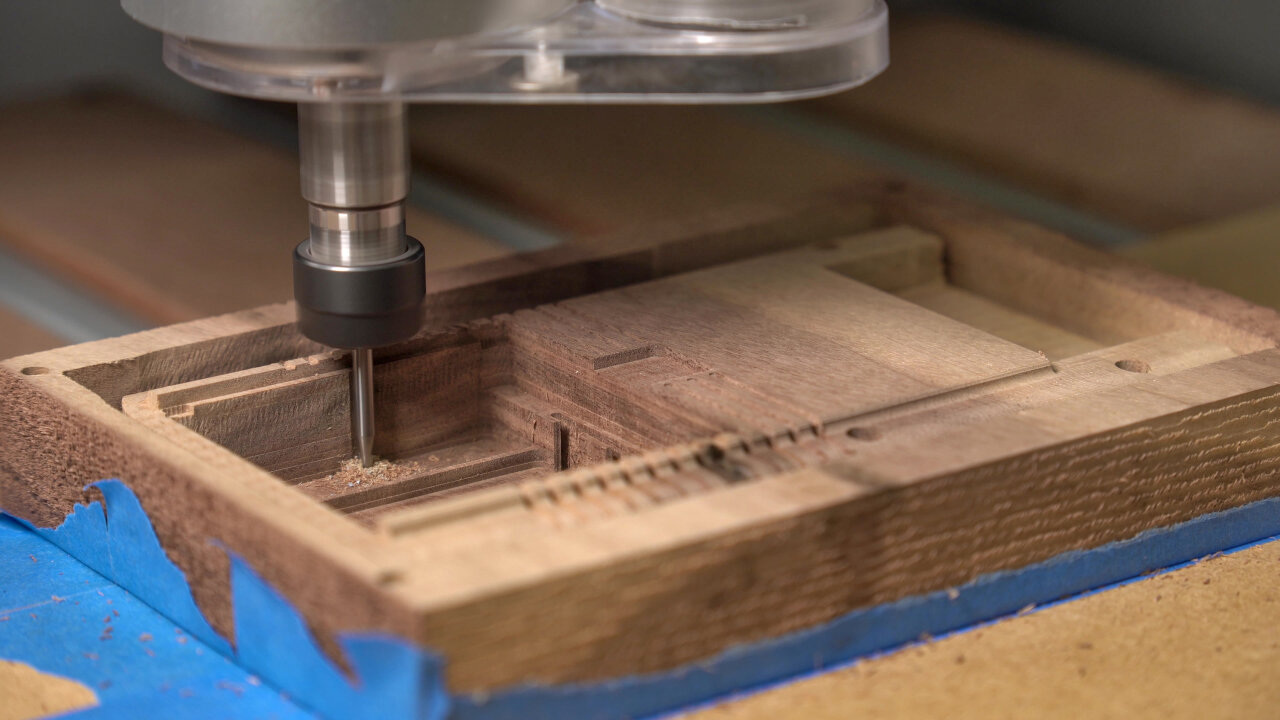
| Finer details of internal geometry | 1.5mm upcut | 002-bottom-inside-2-fine-1.5mm-upcut.gcode | 48 min |
First of all note that as far as I remember, the only reason for using an upcut bit here is that my 1.5mm upcut is a few millimeters longer than my 1.5mm downcut. If this is not a limitation for your tool, you should be fine with a downcut end mill, too, except maybe for some drilling for the screws.
This step adds some details to the power switch part, the battery contact cutouts for the main PCB and some small details like a little cutaway behind one of the screw posts to make space for the speaker cable. It also drills holes for the screws to tap in. In my experience the 1.5mm holes do not hold the thin original screws reliably. On the top half I will later drill 1mm holes, which unfortunately tended to break if a screw is tapped into a pole. So, some experimentation with alternative screws and drilling diameters might be in order here, especially if you plan to use a different kind of wood.
| Purpose | Tool | Gcode | Duration |
|---|---|---|---|
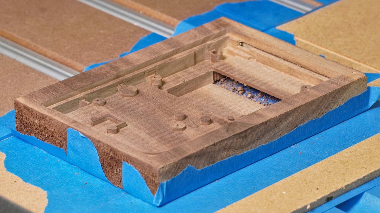
| Profile cut | 3mm downcut | 002-bottom-inside-3-profile-3mm-downcut.gcode | 11 min |
And here is the final profile cut that should meet the profile cut you did on the other side. Note that I use the tape and glue method and did not have to consider any clamps. If you use something else you have to think about bridges if required.
This is where you find out if you have aligned your workpiece properly.
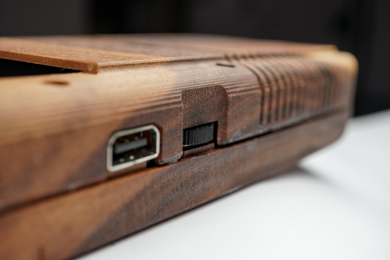
A little detail you should note here is that I did not figure out a reasonable way to create the hole for the AC adapter plug. I ended up manually creating it with a file after the bottom shell was complete.
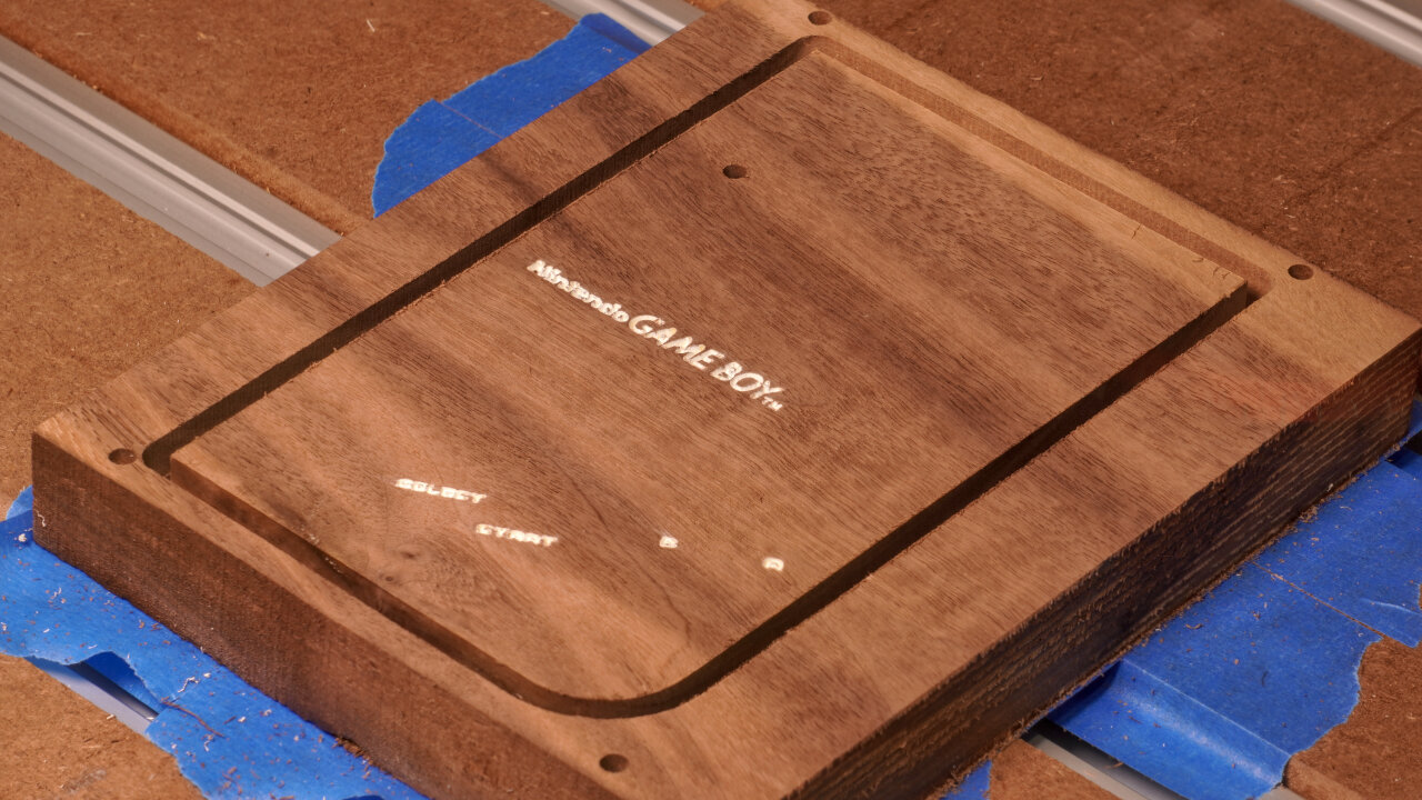
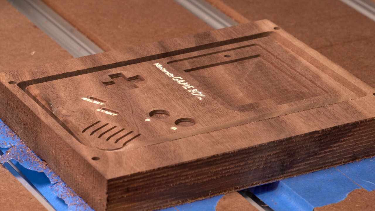
Now it is time for the iconic front of the Game Boy. Please read steps C02 to C03 carefully and think about them. These are the common sign-maker’s method of doing a V-carve, painting everything and then cutting away the excessive paint. I have little experience here and this is the part of my wooden Game Boy that I am absolutely not happy with. My method (or choice of paint or choice of tools or whatever) lead to quite some smearing of the paint and letters that look soft and unfocused.
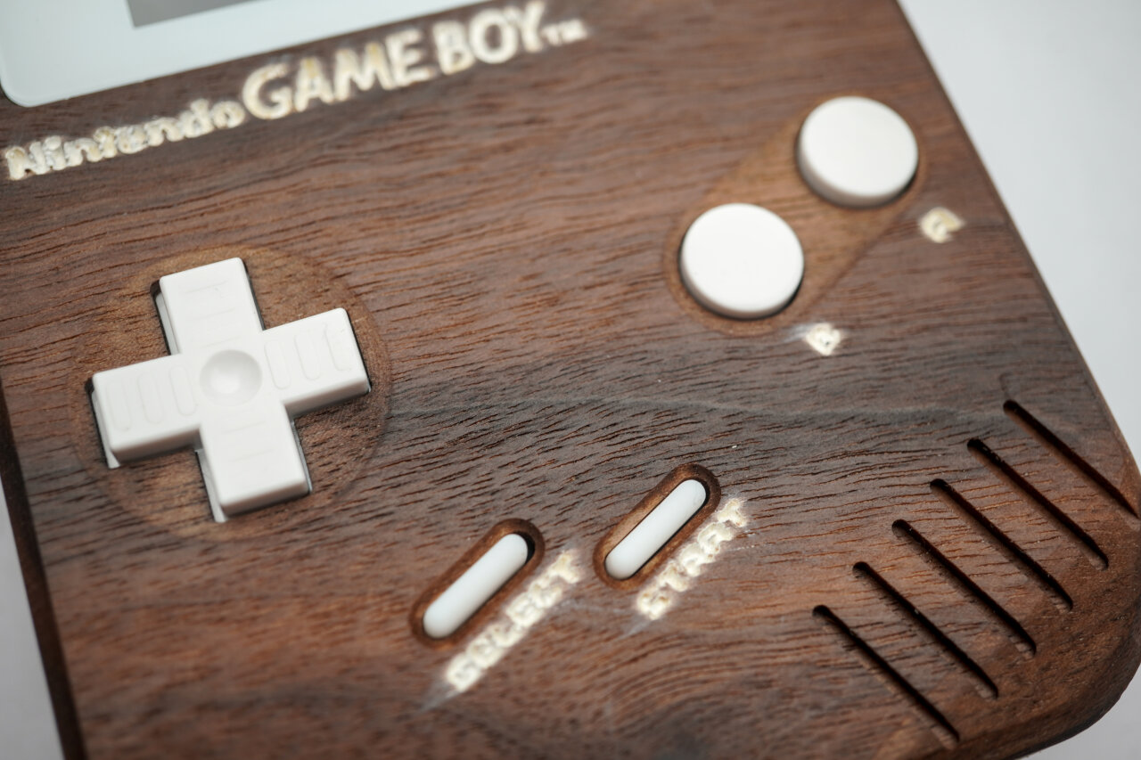
If making the entire wooden Game Boy was less time intensive, I would probably have another try with white epoxy instead of paint. I also notice that many hobby CNCists6 use a belt or disc sander for this instead of a surfacing bit, so maybe that’s part of the problem. If you recognize why this did not work out so nicely in my case, please let me know. Anyhow, below is what I did to get the Nintendo logo and labels onto my Game Boy and you might want to think about a different method.
You will also notice that I did not list a surfacing step. That’s because my method involves V-carving below zero and a later surfacing step anyway. Depending on what you want to do, you might want to surface first.
| Purpose | Tool | Gcode | Duration |
|---|---|---|---|
| Hole to allow deep dive of 1mm bit | 3mm upcut | 1-reference-frame-pockets-3mm-flat-UPCUT.gcode | 5 min |
| Reference for flipping | 1mm upcut | 2-reference-frame-drill-1mm-flat-UPCUT.gcode | 4 min |
Again, the reference for flipping. Again, skip if you prefer a different method. And again, if you use mine, remember to offset zero by 5mm along x and y.
But there is one important difference: If you use my method of painting you will have to remove the workpiece, paint it, replace it and realign it on the same side. That might not work with a flip jig if it cannot be fixed to your machine’s bed.
| Purpose | Tool | Gcode | Duration |
|---|---|---|---|
| Engraving Nintento logo and button labels | 30° V-carving | 003-top-outside-1-label-30deg-v-carve.gcode | 16 min |
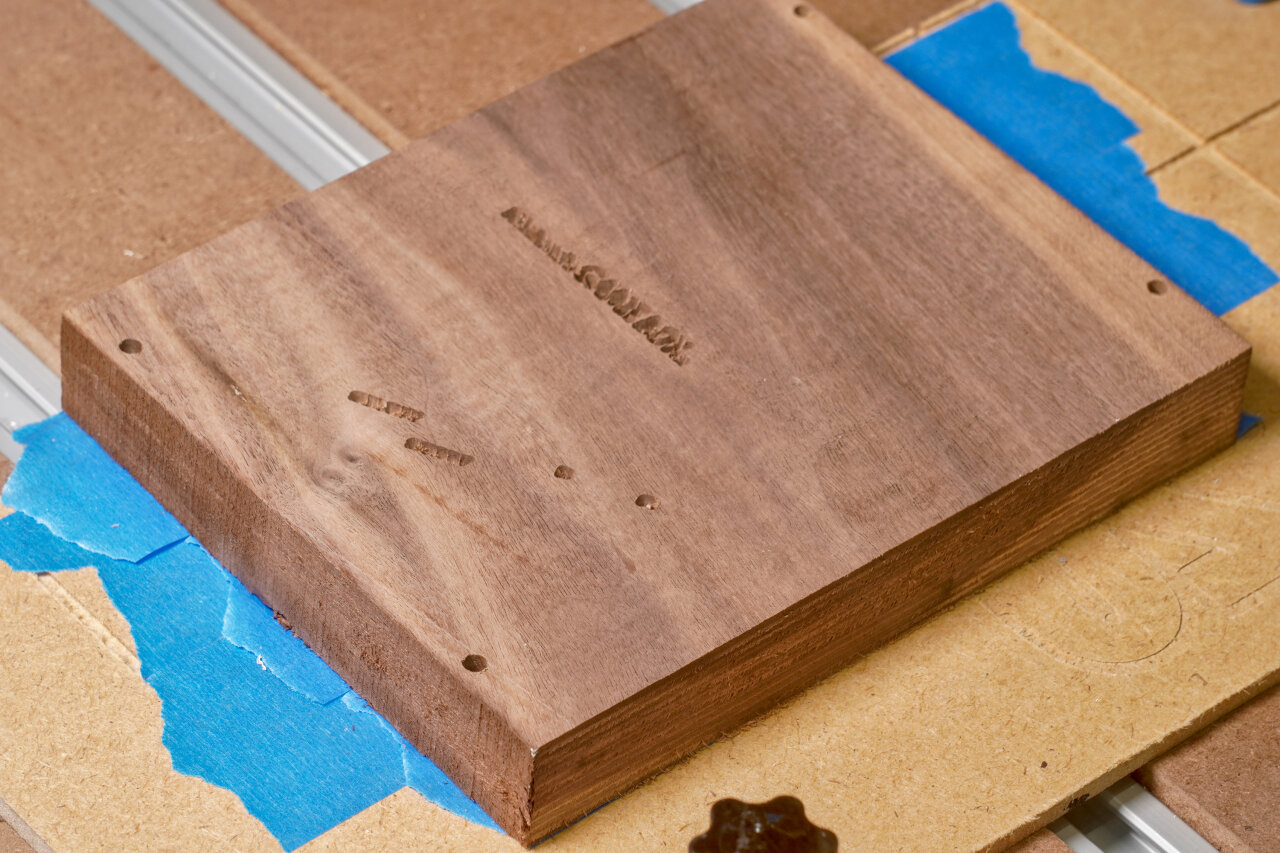
Now, this engraves the Nintendo logo and button labels with a V-shaped bit. I actually ran that toolpath twice: Once starting from the surface (resulting in perfect letters at the surface) and then again starting 2mm below the surface. This is because I will later remove 2mm to return to the perfect letters and remove excessive paint. I did this in two steps because I was not sure if plunging a total of 4mm directly would be too much (now I think it wouldn’t). Also, 2mm might be a bit much, but I had made the observation in earlier tests that white paint enters the wood grain even with a clear coat primer, so I wanted to be safe.
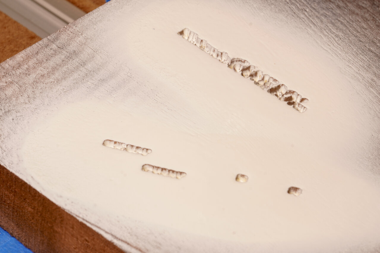
A step that is not a toolpath. Paint your workpiece such that the logo and labels are properly colored. I used spray paint for this and first applied several layers of clear coat as a primer. After it had dried completely, I added several layers of white spray paint. The point of the primer is mostly to prevent white paint from entering the wood grain and showing up several millimeters deeper where it should not be visible. Make sure to seal up every part that could get sprayed with white paint - not only the actual letters.
Any suggestions on improving this method are welcome.
And of course, I had to remove my workpiece for this step. If you apply paint with a brush, you might be able to do this in place.
| Purpose | Tool | Gcode | Duration |
|---|---|---|---|
| Surfacing | Surfacing bit | N/A | 25 min |
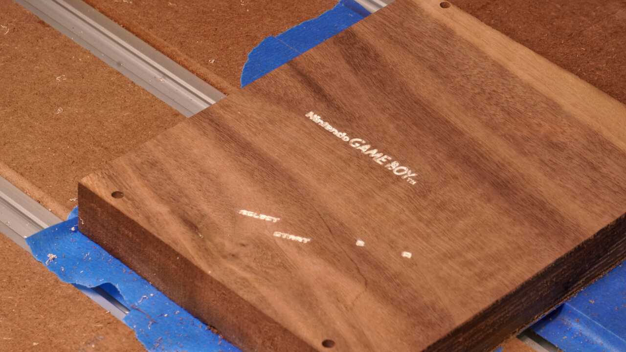
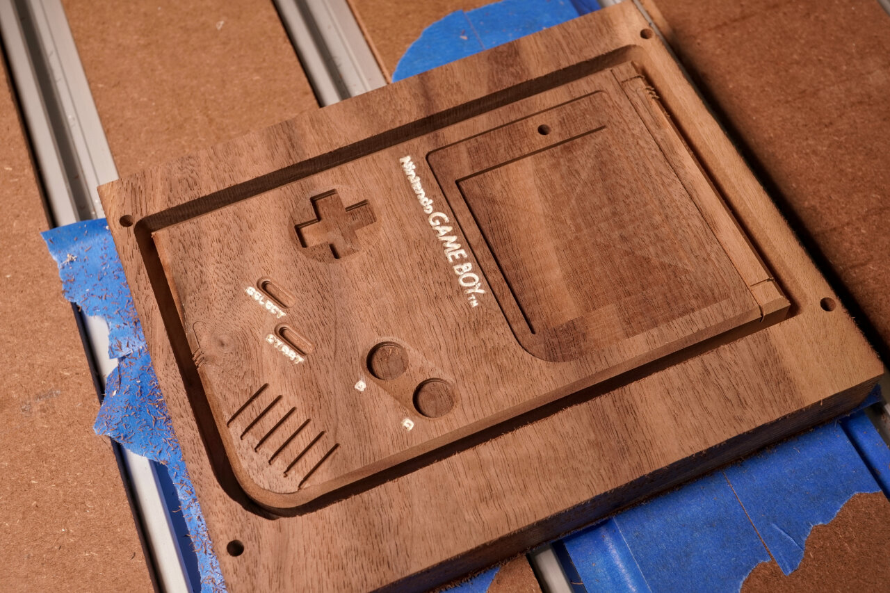
Here I now removed the 2mm that I dove too deep during V-engraving. This removes all the paint outside the carved area, theoretically leaving me with perfect and precise letters. However, as mentioned above I am not entirely happy with the result and you might want to consider alternative methods.
| Purpose | Tool | Gcode | Duration |
|---|---|---|---|
| Profile cut | 3mm upcut | 003-top-outside-2-profile-3mm-upcut.gcode | 24 min |
Next I did a profile cut and again not all the way through. This gives some room for some of the upcoming toolpaths at the edge. Also note that I will chamfer the outline of the Game Boy front, so there is no need for a downcut bit here.
| Purpose | Tool | Gcode | Duration |
|---|---|---|---|
| Screen bezel and LED hole | 3mm downcut | 003-top-outside-3-pockets-3mm-downcut.gcode | 10 min |
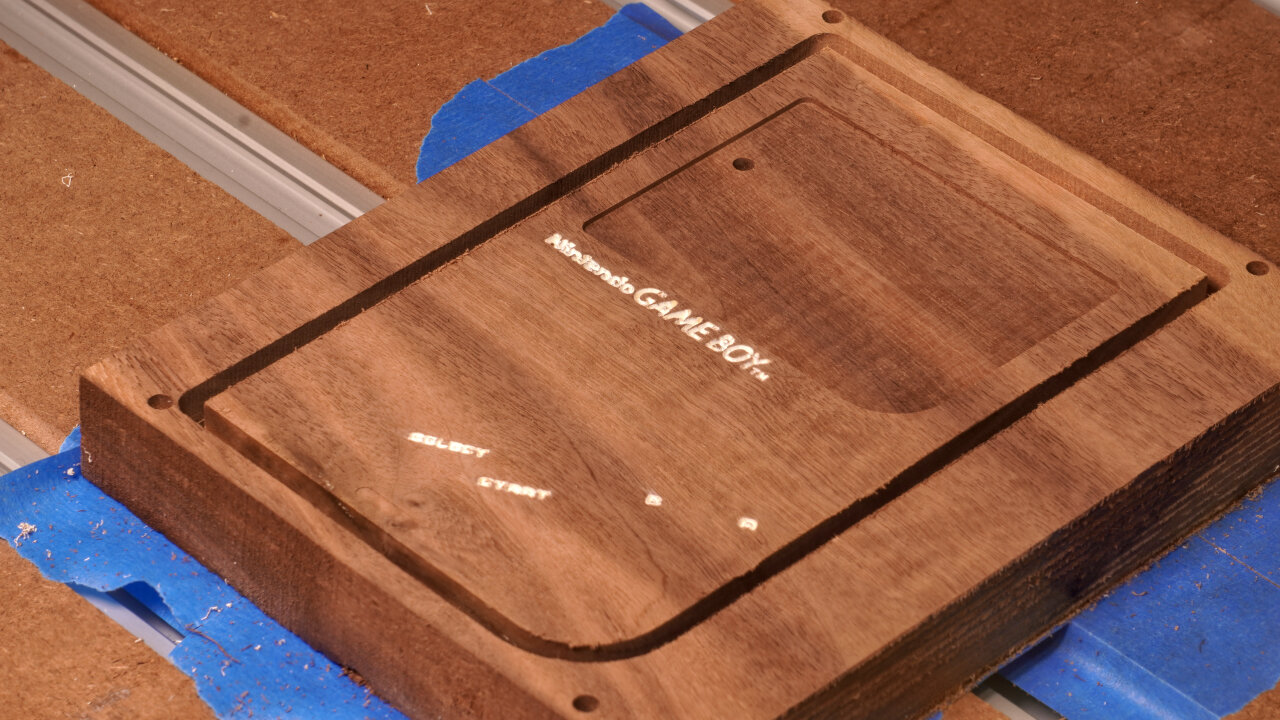
This is a simple shallow pocket for the screen bezel and a little drilling to create the hole for the power LED.
| Purpose | Tool | Gcode | Duration |
|---|---|---|---|
| Pockets for buttons, screen and speaker grill | 1.5mm downcut | 003-top-outside-4-pockets-1.5mm-downcut.gcode | 34 min |
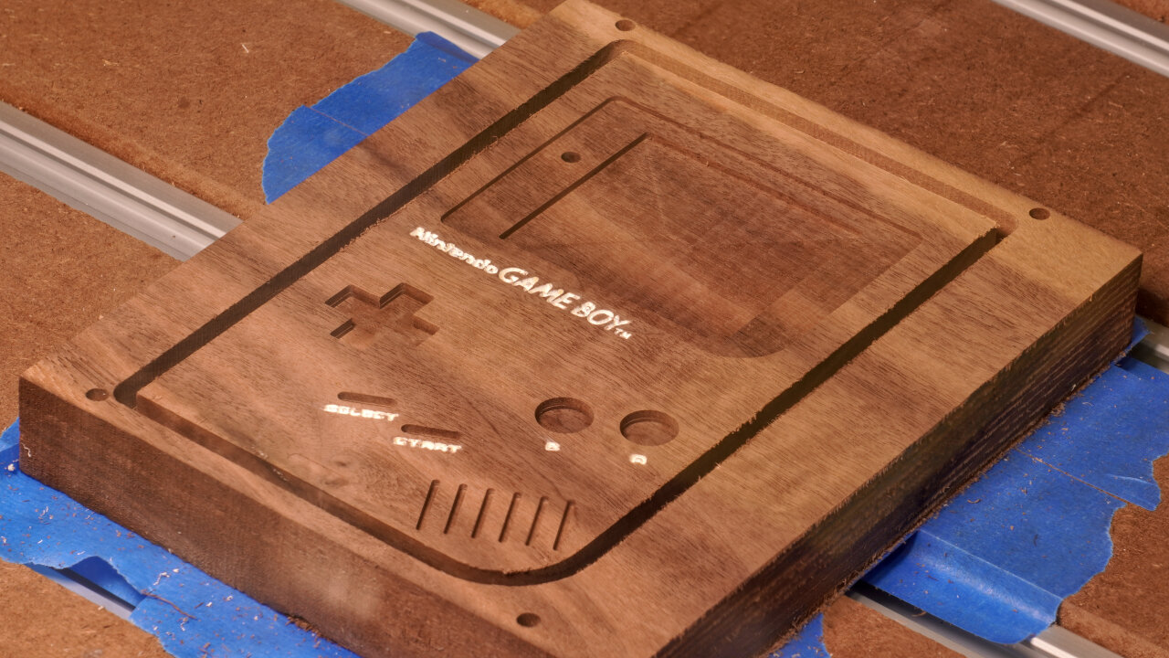
The pocketing of the buttons, the actual screen and the speaker grill is done with a finer bit. In some cases because of thin lines and in some cases to achieve sharper corners. In some cases because it seemed like the buttons should be part of this package.
| Purpose | Tool | Gcode | Duration |
|---|---|---|---|
| Rounded speaker corner and button indents | 3mm ballnose | 003-top-outside-5-indents-3mm-ball.gcode | 21 min |
The Game Boy features a slope at the speaker corner and some smooth indentations around the buttons. These are done with a ballnose bit.
| Purpose | Tool | Gcode | Duration |
|---|---|---|---|
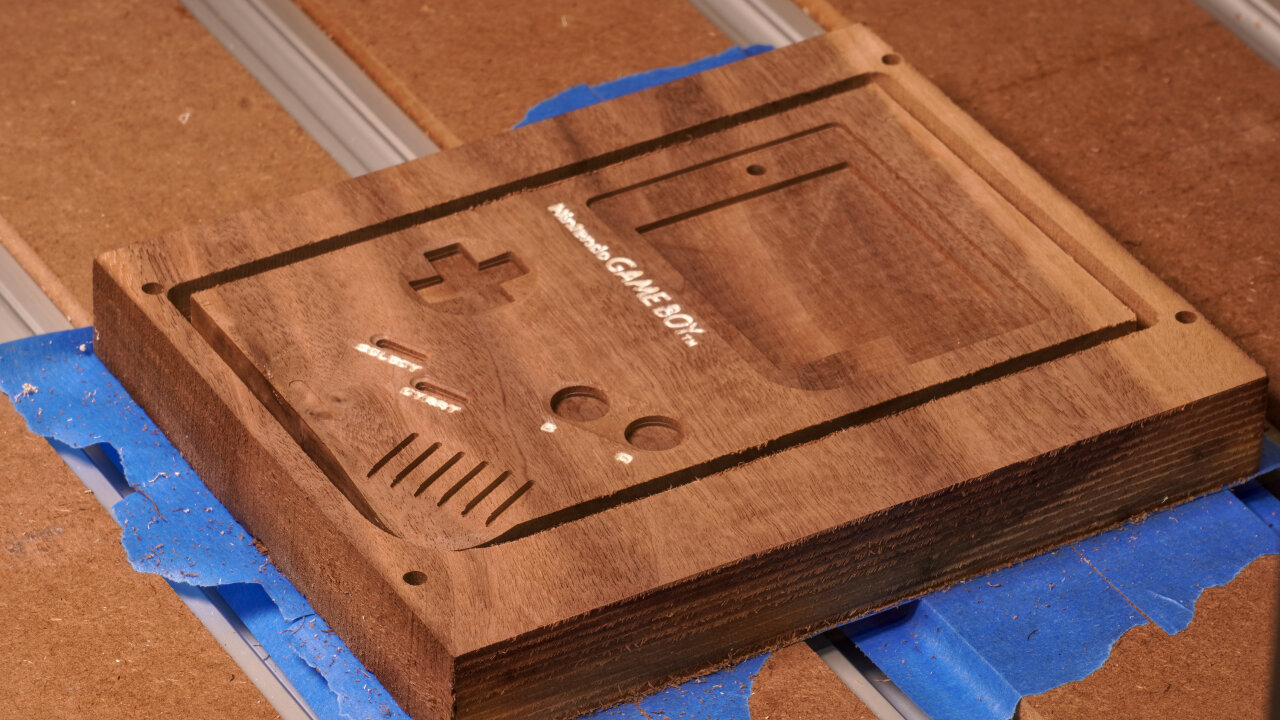
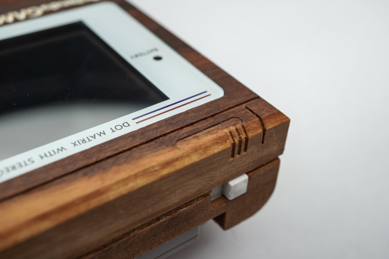
| Outline chamfer | 90° V-carving | 003-top-outside-6-chamfer-90deg.gcode | 2 min |
Finally, my favorite step of most CNC projects. Chamfering. So satisfying.
Unfortunately, there is a mistake in my toolpath. While just following the outline works perfectly for most parts of the Game Boy front, I underestimated the effect of the slope at the speaker corner. A 45° chamfer towards this slight incline resulted in a bit of overhand and a slightly weird look. I sanded5 most of the problem away, but you might want to consider skipping chamfering in this corner.
| Purpose | Tool | Gcode | Duration |
|---|---|---|---|
| Detail decor lines | 1mm upcut | 003-top-outside-7-detail-1mm.gcode | 3 min |
The last step on the outside of the top half just adds the decorative fine lines to the front. This is quick and easy, but note that the only reason for using an upcut bit here is that I simply don’t own a 1mm downcut bit.
Once again it is time to flip your workpiece and align it. And once again remember to offset by 5mm if you use my method.
| Purpose | Tool | Gcode | Duration |
|---|---|---|---|
| Surfacing | Surfacing bit | N/A | 81 min (depends on original thickness) |
If you use wood from the same board as the bottom half of the shell, you probably have to remove a lot of material here. You are aiming for a final thickness of 14.5mm. And this one needs to be very precise. On the bottom half a too thick shell might make it harder to get the battery contacts through to the battery compartment, but on the top half this impacts the top position of your buttons, how deep the screen is below the window and whether your speaker grill goes through (spoiler: mine didn’t).
| Purpose | Tool | Gcode | Duration |
|---|---|---|---|
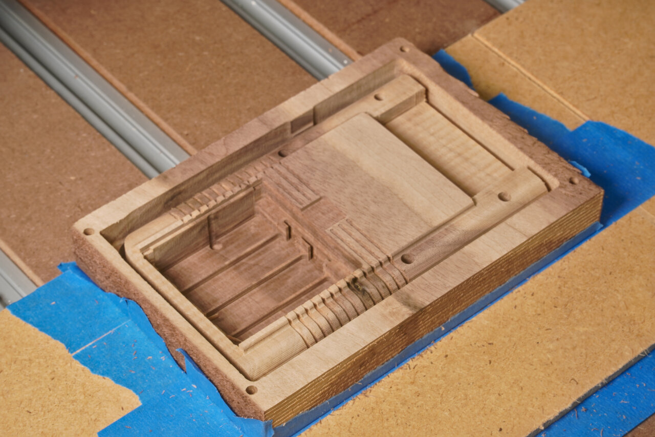
| Pocketing of most internal geometry | 3mm downcut | 004-top-inside-1-pockets-3mm-downcut.gcode | 179 min |
This is the massive pocketing job for the inside, covering most parts. Note that I took some liberty in optimizing the shape for a subtractive process. The original injection mold shape obviously tried to save material while we would like to save on carving away material. So in many parts I left a lot of wood in there, where the original Game Boy just has pockets of air. This should also make it more rigid.
| Purpose | Tool | Gcode | Duration |
|---|---|---|---|
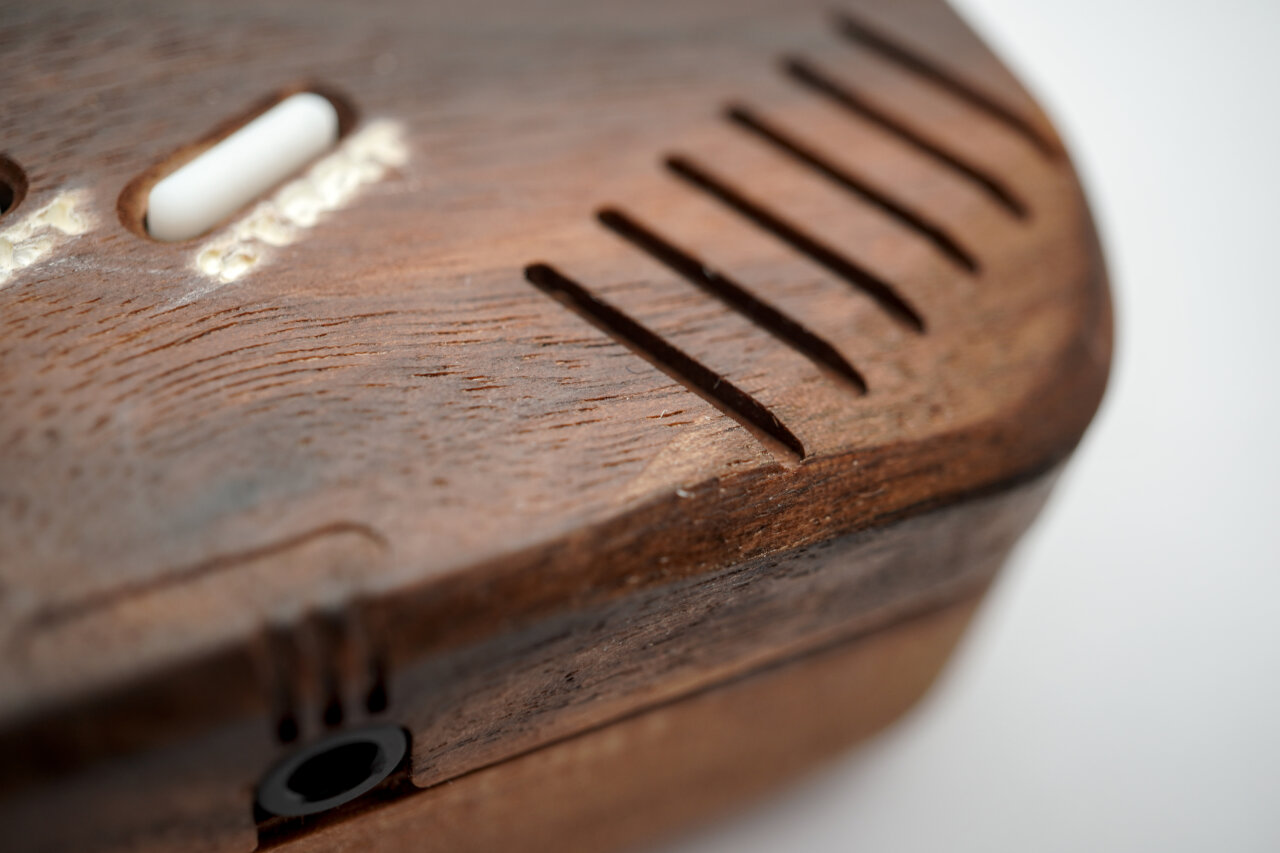
| Details of internal geometry and speaker grill | 1.5mm downcut | 004-top-inside-2-details-1.5mm-downcut.gcode | 15 min |
Adding details that could not be done with a 3mm bit in the previous step. Most notably some details around the buttons and the inside part of the speaker grill. Like on the original, the speaker grill is designed such that the lines on the outside just touch the ones on the inside to create openings. Unfortunately, this just did not work out on my build, but the sound can still be heard very well, so I am not attempting to tinker with it. However, you might want to keep an eye on the problem and maybe move paths closer together.
| Purpose | Tool | Gcode | Duration |
|---|---|---|---|
| Headphone jack | 3mm ballnose | 004-top-inside-3-phone-3mm-ball.gcode | 3 min |
Super short, super simple. The cutout for the headphone jack. I only used a ballnose because this is curved. If you want to save time, you could probably have just done it with a flat end mill in one of the previous steps.
| Purpose | Tool | Gcode | Duration |
|---|---|---|---|
| Profile cut | 3mm downcut | 004-top-inside-4-profile-3mm-downcut.gcode | 5 min |
Finally, the profile cut that meets the one from the front. Hopefully you aligned everything perfectly.
| Purpose | Tool | Gcode | Duration |
|---|---|---|---|
| Screw drilling | 1mm upcut | 004-top-inside-5-drill-1mm.gcode | 4 min |
This drills 1mm holes into the poles for the screws to tap in. As mentioned in step B03, the 1mm holes also did not work perfectly. In my opinion they are better than the 1.5mm holes I used on the bottom half, but the longer poles near the display were split by the screws in this case. If you come up with a better solution, I would like to know.
Wait, we are not done yet. You still need a battery cover. However, since I did not see how the latch of the original Game Boy could be created with a CNC and survive more than one battery changes, I made a very simple design that uses magnets to hold the cover in place.
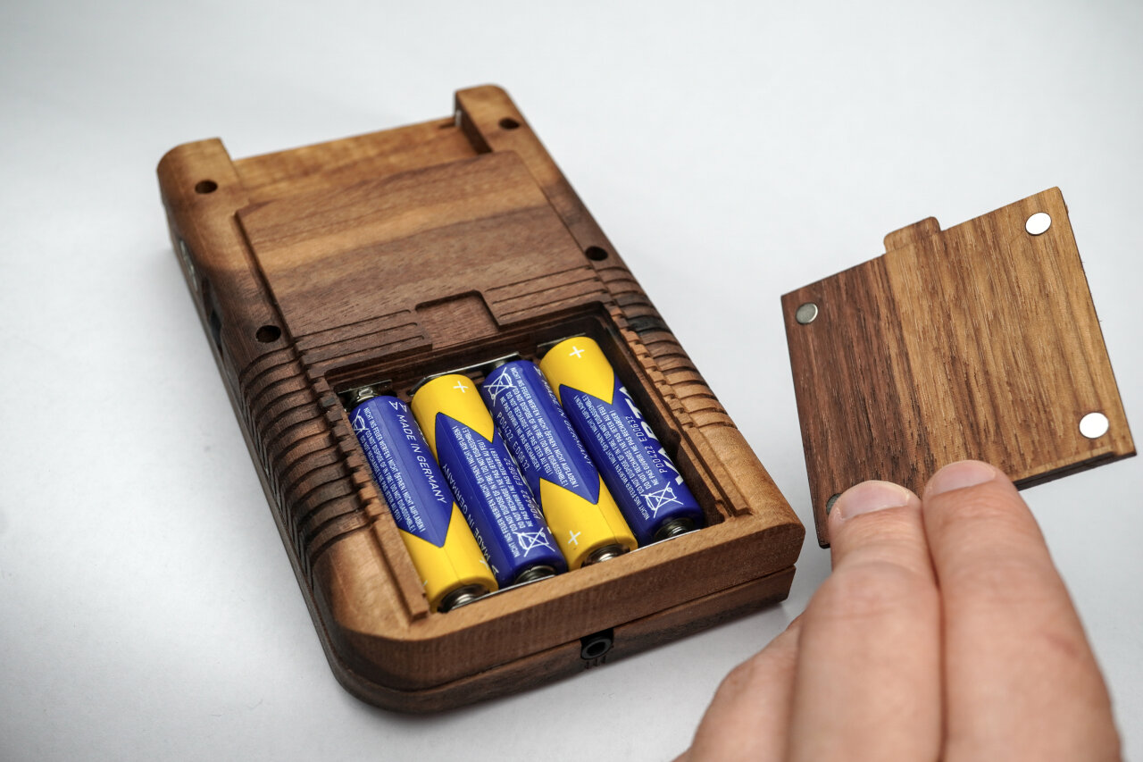
So, this is a rather quick process and you only need a piece of wood with an even thickness of about 4mm to 5mm. The magnets should be 1mm thick discs with a diameter of 5mm and I could simply press them into the pockets.
| Purpose | Tool | Gcode | Duration |
|---|---|---|---|
| Reference for flipping | 1.5mm downcut | lid_outside_0_references_1.5mm.gcode | 1 min |
| Decor lines | 1.5mm downcut | lid_outside_1_grooves_1.5mm_downcut.gcode | 3 min |
This step cuts references for flipping and adds the decorative lines on the outside of the battery cover. That’s it. Nothing more to see here and it is time to flip the wood piece to the other side.
| Purpose | Tool | Gcode | Duration |
|---|---|---|---|
| Cut down everything but lip | 1.5mm downcut | lid_bottom-1-1.5mm-start4.5mmabove-bottom.gcode | 42 min |
| Flatten handle | 1.5mm downcut | lid_bottom-2-1.5mm.gcode | 1 min |
| Magnet pockets | 1.5mm downcut | lid_bottom-3-1.5mm.gcode | 1 min |
| Profile cut | 1.5mm downcut | lid_bottom-4-profile-1.5mm.gcode | 2 min |
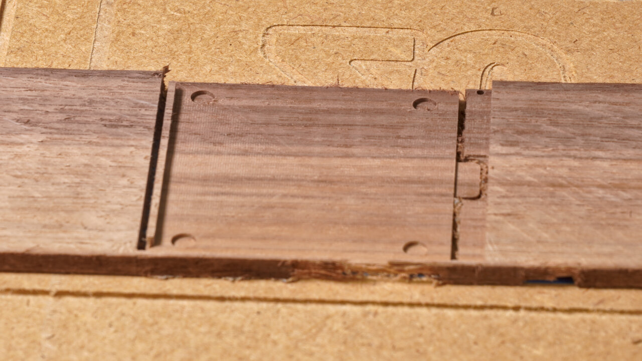
This of course could have been one gcode file, but I couldn’t be bothered for this little part at the end of all the work. In this step you will flatten the cover to the desired thickness while leaving a lip that prevents it from sliding out. Here you also create the pockets for the magnets and do the profile cut, which will go below your workpiece into your spoil board.
That’s it, the hard part is done. You should sand5 any problematic or rough parts and apply wood finish. I use boiled Linseed oil, but there are many options7 out there and many people with more experience in selecting them.
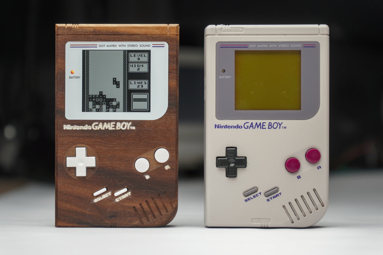
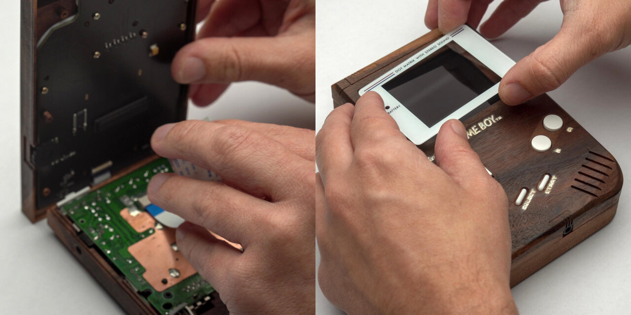
After that, you should be able to simply disassemble a Game Boy and replace its shell with your new wooden one.
I actually only used the original mainboard of a broken Game Boy from ebay and aftermarket parts for everything else, so let me show you a few details.
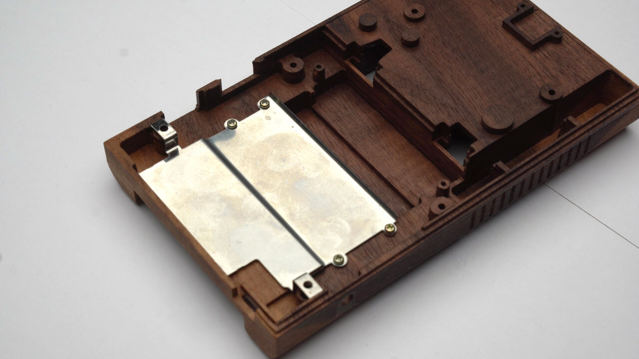
First of all, the metal shield between mainboard and cartridge slot can simply be screwed into the wooden shell with the original screws (ok, those are also original parts). You just might need to file away some edges to fit the bent parts around the screw posts.
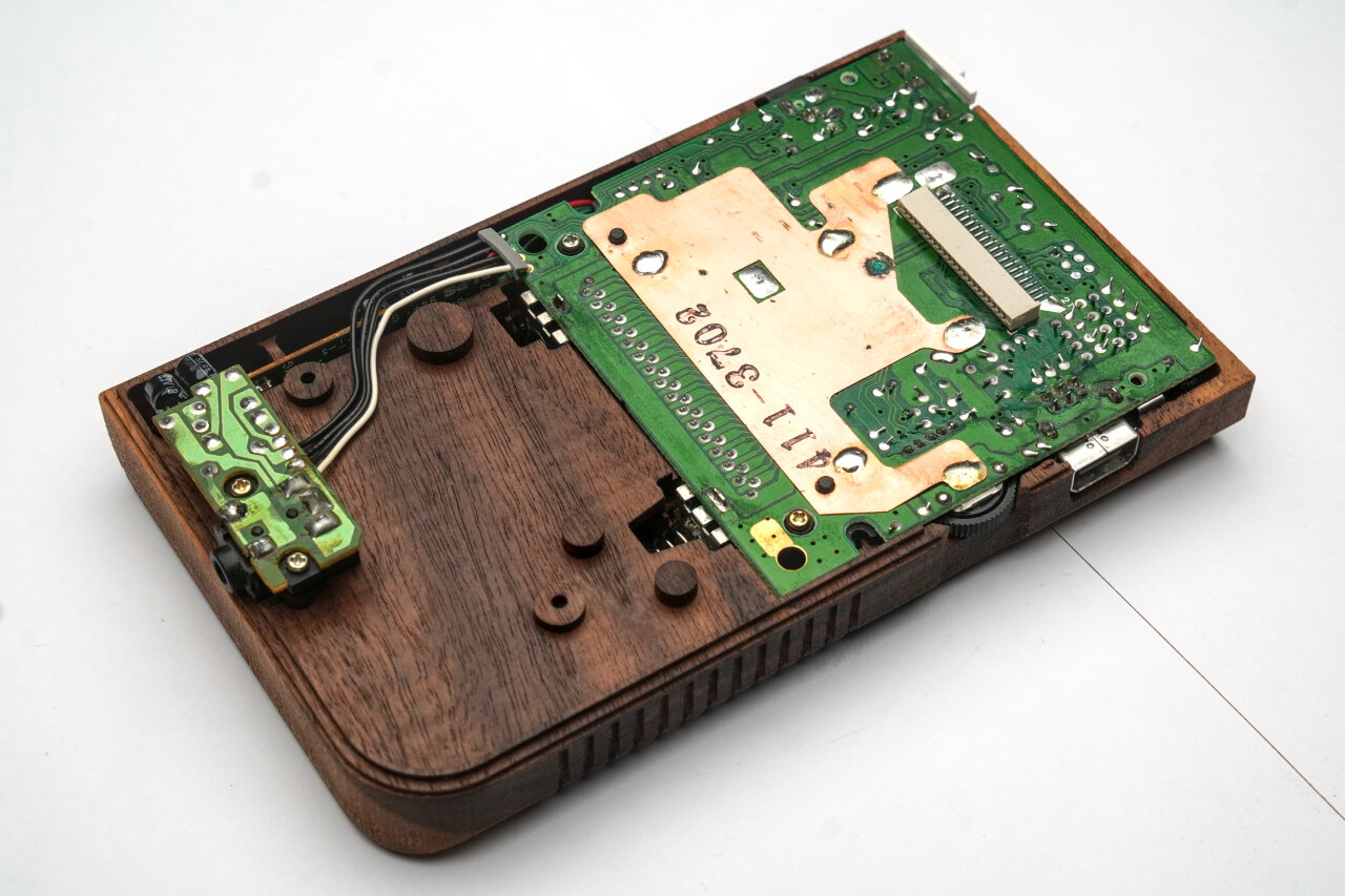
The same is true for the PCB and the attached boards. However, here I already had some problems of screws not holding well in the 1.5mm drills I did on the bottom half. The 1mm drills on the top half worked better, but posts tended to break there, so be careful here.
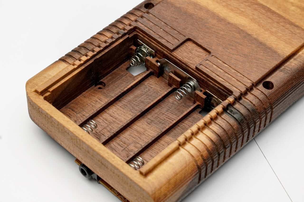
In the battery compartment you just have to insert the additional contacts. The outer contacts are already there from the PCB. Note, that in contrast to the photo above I had to put a thin piece of cardboard behind the contacts to press them against the batteries.
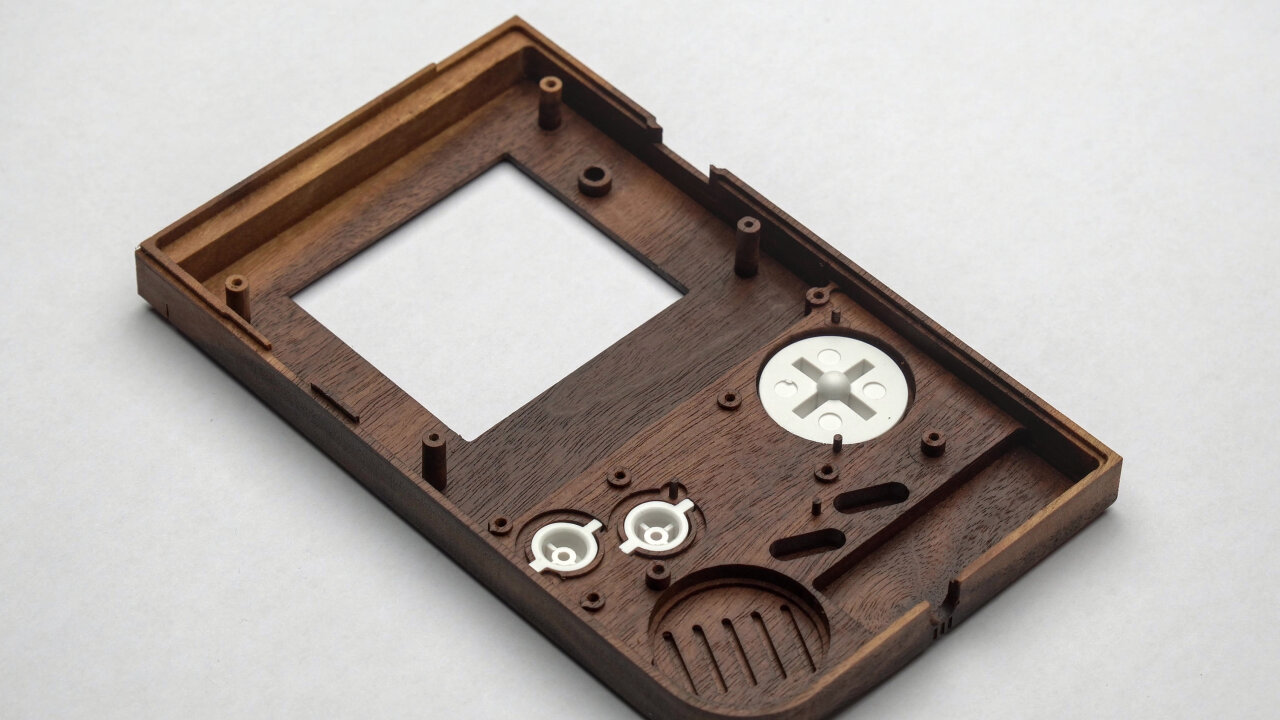
The white aftermarket plastic buttons fit perfectly, but there are some tricky aspects to the silicone pads between the buttons and the PCB. First of all, there are very thin poles that help aligning the silicone pads. They do not have to hold against any force, but still you should be careful to not break them as they really help putting everything together. Second, the silicone pad of the A and B button has a somewhat complex line around the buttons that looks roughly like a figure eight with an additional outline. I did not reproduce the slit for the additional outline, which prevents it from being flush on the wood by default. You either have to add a carving for the outline or cut the outline from the silicone pad like I did with my aftermarket pads.
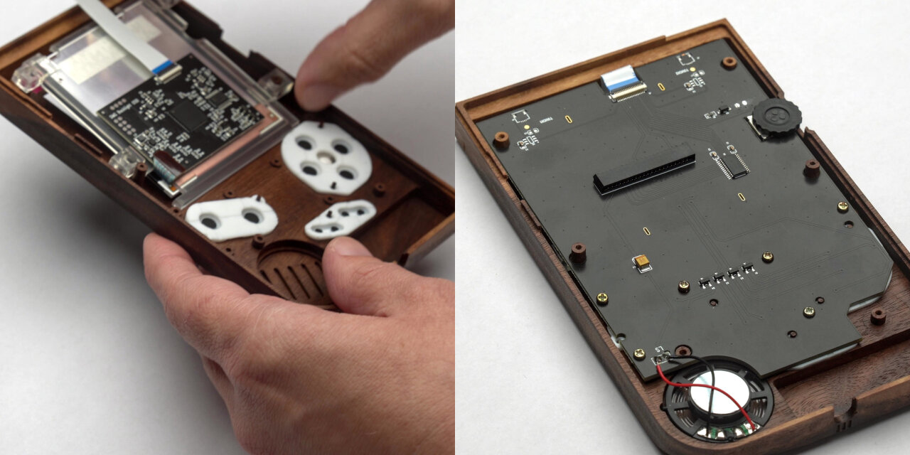
For the display I decided against using an original screen8 and picked up a modern IPS mod kit instead. Note, that I made a few simplifications and optimizations to my design to fit this display. In particular, the contrast wheel has an additional lip on the original Game Boy and there are additional posts at the top of the display which I did not model. I think that an original display also fits, but you might look into this if you want to use a different screen.
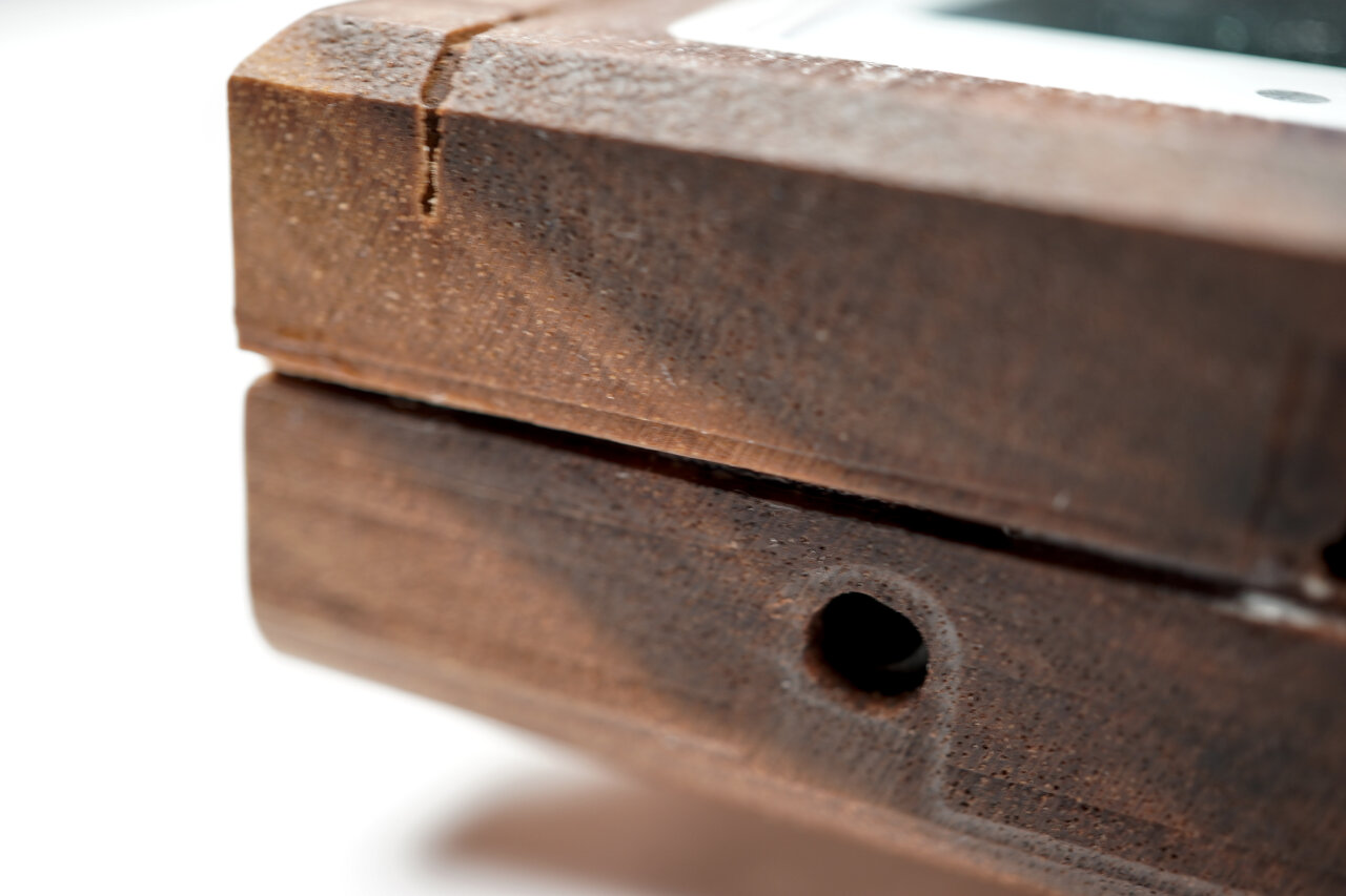
I did not find a good way to add a small pole right next to the large pole in the bottom left corner of the display (viewed from the inside). Unfortunately, the plastic holder for the display that comes with the kit uses this pole as one of four poles that hold it in place. However, it still seems to be very stable when using only three of those poles. The PCB of the kit can simply be screwed into the shell with original screws and holds very well with the 1mm holes I drilled here. Only problem is that the poles below the display split in the process. So,… well… I am not sure what to make of this. The PCB is held very securely, but I am not sure if I will eventually find cracks in the case from the other screws over time.
Finally, all you need to do is to connect the two halves and glue the display cover into the screen bezel. There is just one major catch: For me the two halves were too tight and the screws could not properly hold them together. I am not sure if filing and sanding some parts for a better fit will help and if tapping the original screws into 1mm drill holes instead of the 1.5mm ones I have in the bottom half might be enough, but I only found a somewhat nasty solution: Gluing the case with wood glue.
While I still love the resulting Game Boy and while it feels very solid and reliable, it bugs me a little to have a slight gap on one side and a bit of glue residue. If I ever want to reach the parts inside, I probably have to crack the case open, but at least no original parts had to be glued and could simply be replaced in the original Game Boy. Still, it would be nicer if I could just open the shell in case I ever need to do maintenance inside.
When I started this project, I somewhat underestimated the amount of effort and time that had to go into it. But I also totally underestimated how stunning the result would be. At the moment it just sits on a sideboard in my office and I have to grin and pick it up each time I walk by it.
Initially, I planned to also machine the buttons out of a brighter type of wood. However, I did not find a good way to create a transparent display cover with matching wood applications and eventually settled for white aftermarket buttons and a matching display cover. Now that I see the result, I think that this was a good decision as it helps to define the shape and look.
Also, the Game Boy plays quite well. If I am looking for any playability problem, maybe the buttons trigger a little bit below their tactile response point and I am not entirely certain if this is to be expected. But this Game Boy will not be my daily gaming platform anyways. This is meant to be presented somewhere. At the moment I am thinking of making an acrylic stand for it and use my WiFi cartridge to use it as a status display in a prominent location.
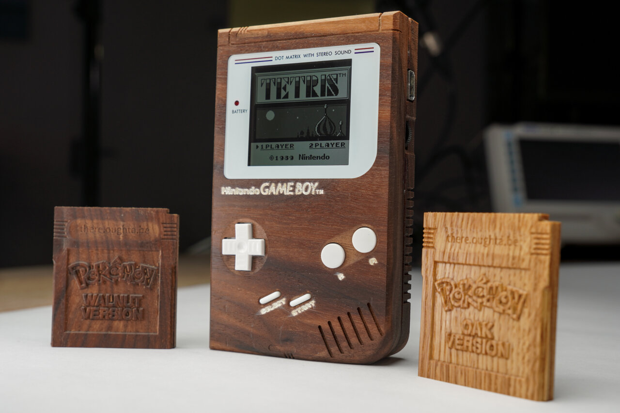
Oh, and if you have been wondering about the wooden Pokemon cartridges: Those are based on the cartridge I published earlier with several improvements to the toolpaths (man, I learned so much from the Game Boy project) and the Pokemon logo added. These versions are also in the GitHub repository for the wooden Game Boy, but I did not add more documentation for it. If you got to this point, I am sure you can figure it out… :)
Even though I am a huge FOSS fan I am absolutely willing to pay for good software. But I am not willing to do so for software that does not even run on my OS of choice. I do not expect that CAMs are written for Linux, I just don’t want to pay several hundred bucks on software that then turns out to crash regularly due to emulation. ↩
Much longer than you would expect. The paths have to be closer to still overlap, but you also need to reduce the feed rate of your machine as the smaller bit cannot take as much material per rotation. Even worse: If you cannot increase the rotation speed, the smaller diameter also means that the tangential velocity of the cutting edges at the smaller diameter is significantly reduced. I would say that going from a 3mm bit to a 1mm bit will require about 9 times as much time to clear the same amount of material. ↩
Noticed the blue tape on my dust shoe? That’s where the machine drove the dust shoe directly down into a clamp from above. Did not stop or even slow down. After all, the motors are designed to press a mill into hard wood or even some metal, so it probably did not even notice the plastic cover of the dust shoe. ↩
Never used that word before. Hope I applied it correctly. ↩
Is that a word? ↩
My main reason for using Linseed oil is that I already used it as non-toxic option on things I made for my kids. I like the natural look of it compared to a clear coat, but that’s all the input I have here. I am not doing this long enough to say how well it protects my wooden Game Boy. ↩
In the past I made a point of using an unmodified original Game Boy to demonstrate that my hacks work with original hardware. No reason to that on a modded Game Boy like this. ↩