
19 August 2020
Instead of watering my lawn manually, I created the automated irrigation system that you can see in the following video.
As you will see, just a simple system that turns the water on or off was not sufficient. I will show you all aspects of this Arduino based system in this article and provide the source code.
There are plenty of projects out there that automate irrigation. Many focus on the problem of automatically reacting to dry soil by opening a single valve, but a fully automated system with one valve is not what I want for my lawn. I do not want the sprinklers to turn on unexpectedly and I had to solve a different type of problem: Managing a specific irrigation program with individual control over each sprinkler.
For my setup there are two problems I had to address. The first one is that the very first pipe that is directly attached to our groundwater pump is too thin to support all sprinklers required to cover our lawn. The pipe goes through the wall of our garage and at some point I will probably replace it with a larger one, but even then the output current will be too limited to run everything at once. I need to run the sprinkler sequentially to achieve sufficient pressure to get the range I need.
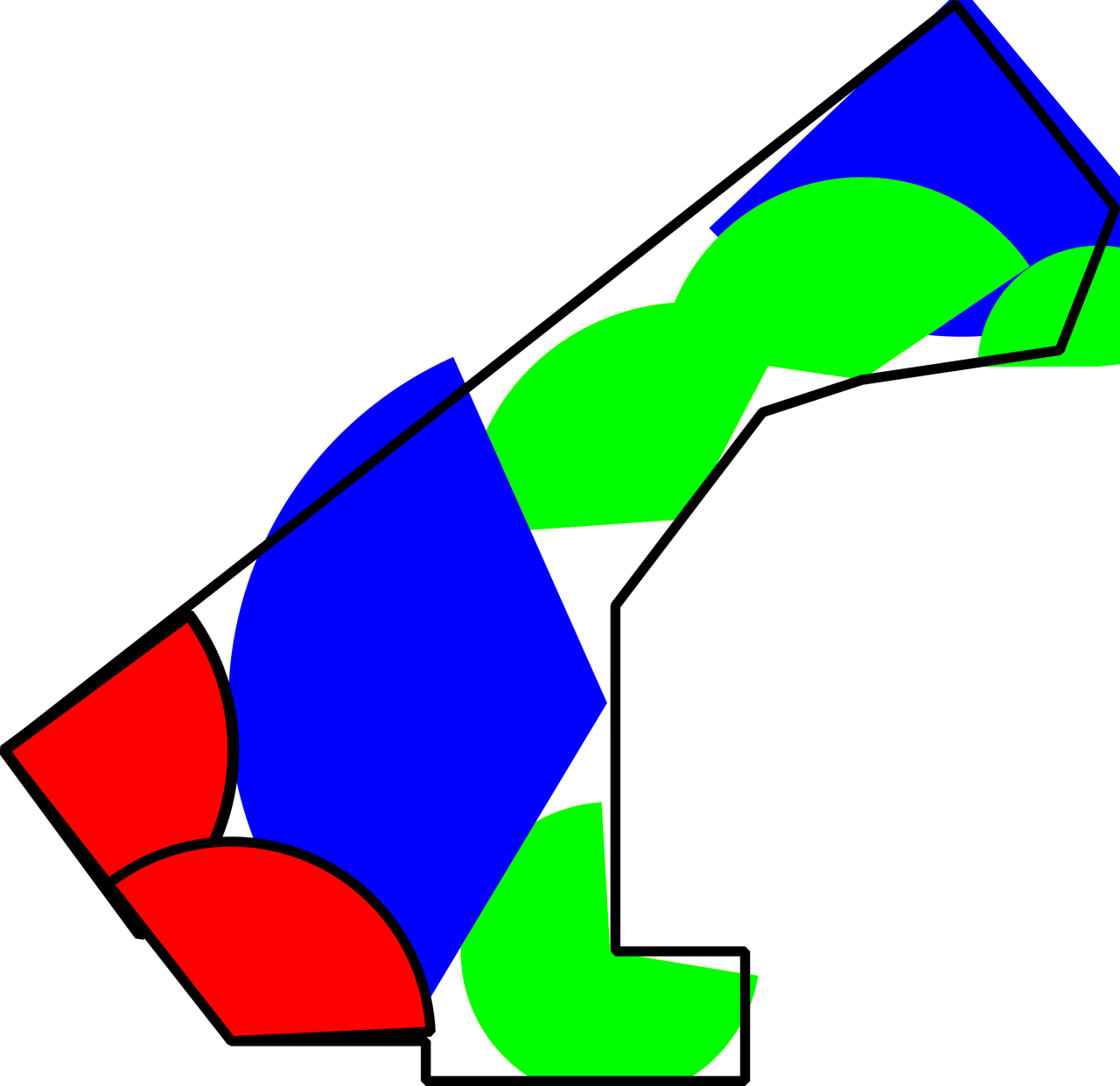
The second problem is that our lawn has a rather irregular shape. I cannot simply place two sprinklers with a rectangular pattern in the center to cover it properly. Also, I wanted to avoid sprinklers in the lawn itself, so I designed the irrigation system such that the sprinklers can reach every point from the patches at the sides. I arrived at a design that uses many different sprinklers with different sectors and ranges. Their output could be reduced such that they provide the same amount of water per area per time but since the output from the pump is already limited, this would mean that sufficient watering takes even longer. Instead, I run all sprinklers at maximum output, which means that I have to individually control their active duration to make sure that the entire lawn is irrigated evenly.
So, in contrast to most irrigation systems, I need less actual automation and more control over individual sprinklers or sprinkler groups.
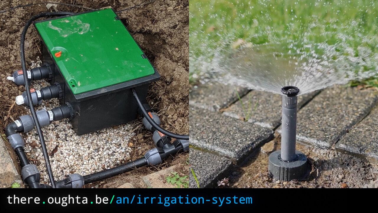
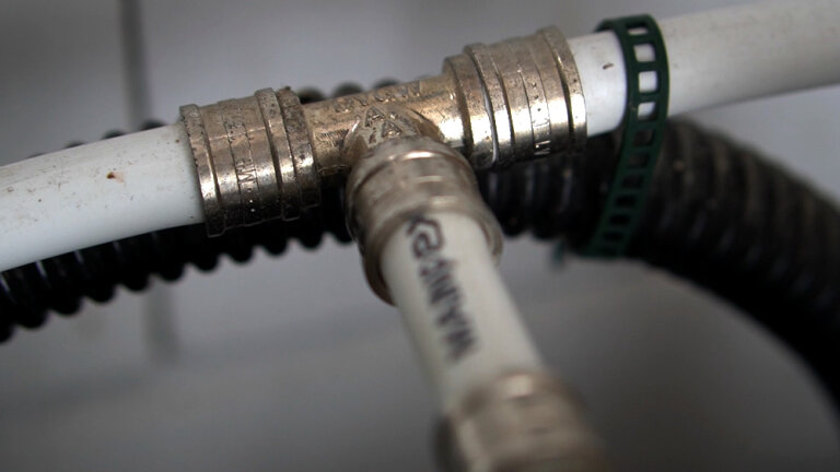
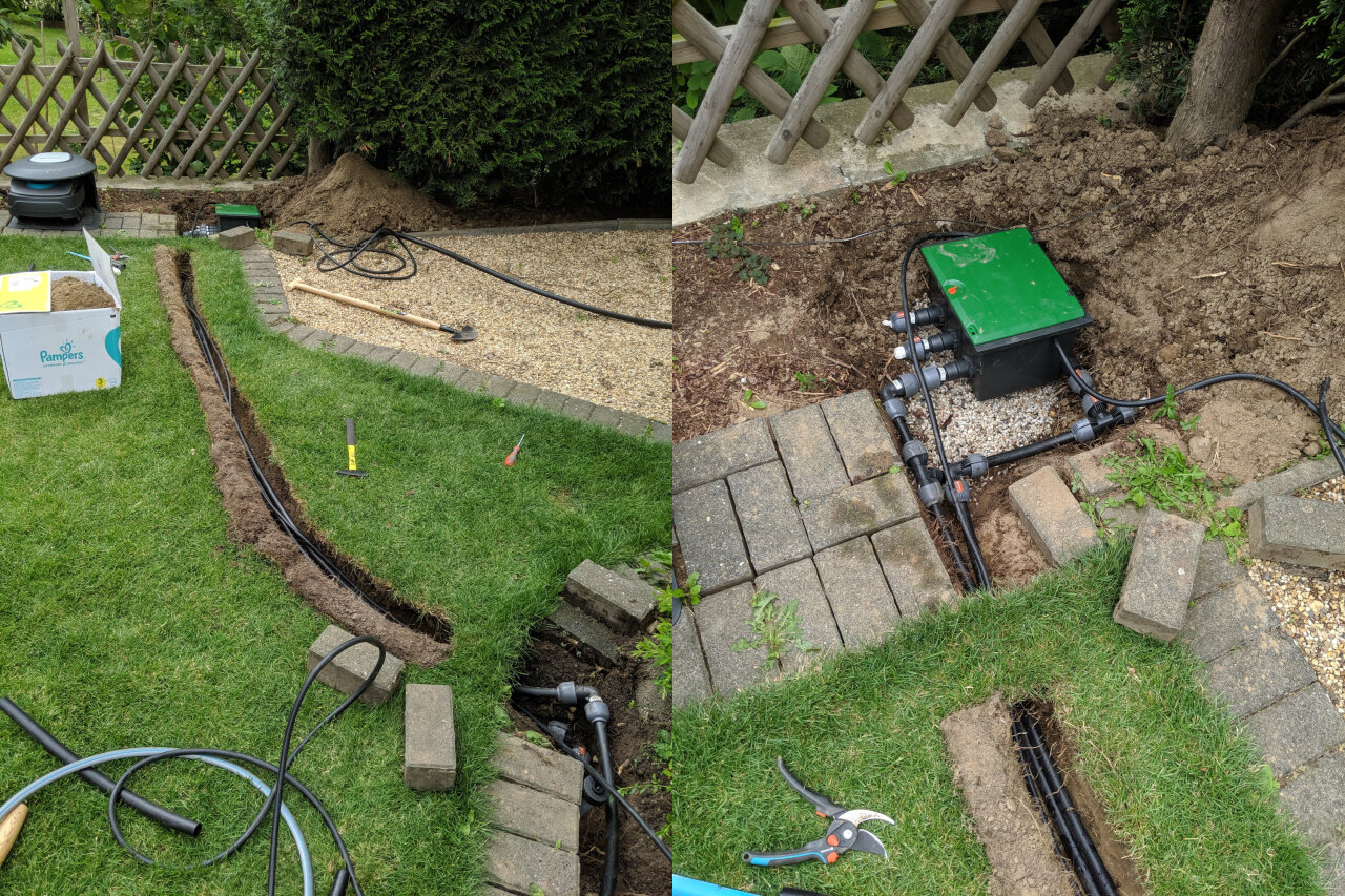
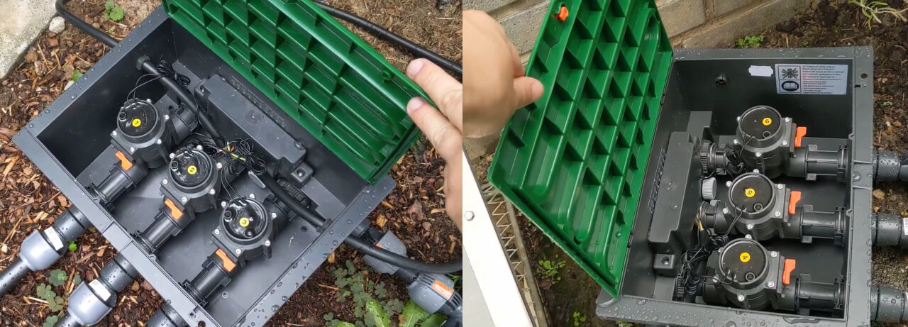
The sprinkler network is mostly based on the Gardena sprinkler system. The pipes run underground to supply valve boxes, from which again pipes run to supply individual or small groups of sprinklers. For each independent pipe and the valve boxes I also had to install drain valves that automatically open if the pressure drops. This allows the pipe to empty through gravel drains (that also had to be created) when the system is turned off, so the pipes do not break in winter due to freezing water inside.
The entire lawn could be covered by eight sprinklers. Four small Gardena S80, two slightly larger T100 and two massive1 T200. All of them are placed at the side of the lawn and limited to a sector that is usually close to a half-circle or quarter-circle. This way, every patch of grass is covered with barely any water being wasted on paving or fencing.
However, as they are all set to maximum output, we need some logic to achieve a uniform irrigation.
The system uses a total of six valves2 to address the sprinklers. Those are 24V magnetic valves from Gardena and housed in underground valve boxes in groups of three.
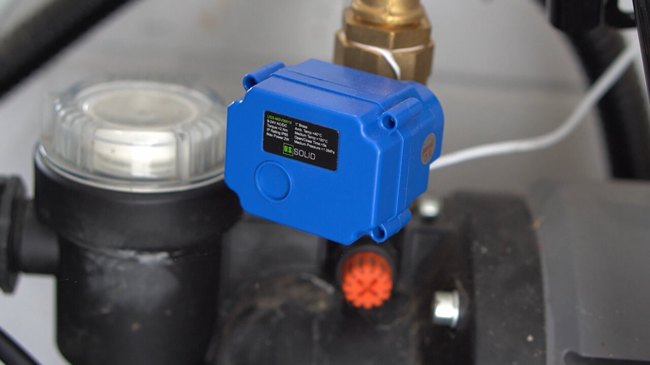
There is also a U.S. Solid normally closed ball valve right at the output of the groundwater pump as a safety measure. The pump turns on automatically if the pressure at its output drops and turns off if the maximum pressure is reached, so this would already work fine if I closed all the valves to the sprinklers. However, I prefer to also close the pipe at the source to avoid a flooded garden due to any leakage at the rather large pipe network or due to my son opening the other water tap3.
So, the system supports two modes, that both run on a timer. We can set a target duration (in half hour steps up to eight hours) during which the main valve stays open without the sprinklers. More importantly, we can also tell the system to uniformly water the lawn in the given time, for which I have set up an irrigation program specific to my sprinkler setup. To do so, I have to determine the number of irrigation steps, the relative durations for each step and the sprinklers that are active in each step (the entire code is linked at the end of the article):
1
2
3
float intervals[] = {0.16, 0.08,     0.08, 0.04, 0.15, 0.49}; //fraction of active duration, index is step
int steps[] =       {   2,    4, 6 + 0x30,    6,    1,    5}; //Order of valves in auto mode
int nSteps = 6;
So, we have six steps and in the array intervals I define a duration for each step. If the system runs one cycle of these six steps, the duration for each step can be calculated by multiplying the interval from intervals with the total duration of the cycle. The steps array defines which sprinkler (number 1 to 6) is active in each step. So, for example, if we have an irrigation cycle with a duration of 120 minutes, the first step would run sprinkler 2 for 0.16 * 120min = 19 minutes. If a longer total duration is set, the system automatically splits it into several cycles of shorter length, so the sequence of steps can be repeated several times. A single step can also open two sprinkler valves4 if steps defines another sprinkler (again, 1 to 6) in the higher nibble5.
The numbers seem a bit arbitrary here, but I measured the output of each sprinkler group by placing basins on the lawn and the order is selected such that those sprinklers start first that water the part of the lawn that first receives shadows in the evening. Sprinklers 3 and 6 are both small S80 models, so I can run both at the same time, but I split this into two steps to allow sprinkler 6 to run longer, because the patch of lawn at sprinkler six turned out rather dry as it is almost always in the sun while the part at sprinkler 3 is almost always in the shadow.
So, we have the sprinkler, piping and a bunch of valves. What’s missing is the brains and power supply, which are simply screwed to a wooden board at the wall inside our garage.
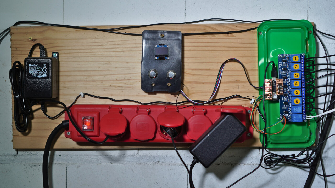
The brains in this case is an Arduino Nano 33 IoT, which is the first time I used one of these. In principle, you should be able to use pretty much any microcontroller, but if you want to control it via Wifi, you quite obviously need one with Wifi capabilities. If you want to run my code with only minor modifications, you probably also want to go for the Arduino, but if you do not mind some adaptation, an ESP32 would probably be the cheaper and much more common choice.
The power supply is just a 26V (AC) supply by Hunter. If it is connected to any of the valves, the valve opens. As the Arduino obviously cannot handle this voltage directly, I am using a readily assembled 8 channel relay board by Kuman. I rather crudely soldered a bridge with sockets, to connect the Arduino pins to the relay board. Also, to supply the relay board with power (not to be confused with the 24V-26V switched by the relays), we simply share the USB power through the +5V pin of the Arduino (which requires soldering a jumper pad).
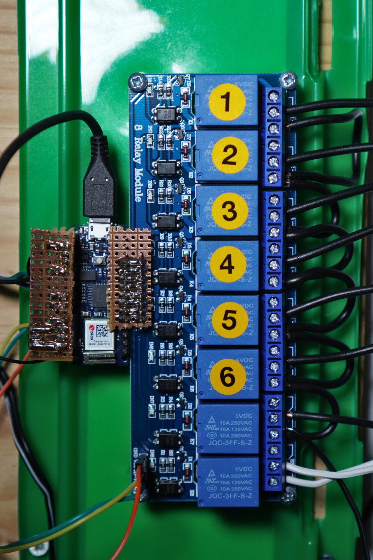
Relay channels 1 to 6 correspond to the Gardena valves controlling the sprinklers. Channel 7 controls the main valve and channel 8 is not related to this project - it was just another relay available in the garage for a project that I might present another time… Here is the Pinout for the Arduino:
| Function | Pin |
|---|---|
| Valve sprinkler 1 | D9 |
| Valve sprinkler 2 | D8 |
| Valve sprinkler 3 | D7 |
| Valve sprinkler 4 | D6 |
| Valve sprinkler 5 | D5 |
| Valve sprinkler 6 | D4 |
| Main valve | D3 |
| Left Button | A1 (used as D15 with interrupt) |
| Right Button | A7 (used as D21 with interrupt) |
| Display | SDA and SCL |
As you see, there are also two buttons and an OLED display connected to the Arduino (all supplied via its 3.3V output), which I will discuss further below.
The main method to control the irrigation system is via Wifi. The Arduino automatically connects to our network and connects to the MQTT broker of my openHAB installation. It subscribes to several topics to allow controlling the irrigation system via MQTT and also posts MQTT messages to other topics to share status changes.
| MQTT topic | Function |
|---|---|
| watercontrol/setAuto | Open main valve and set a duration (or close it by setting it to zero) |
| watercontrol/setSprinkler | Enable/disable automated irrigation |
| watercontrol/setState | Enable a specific sprinkler ignoring the current cycle position (or disable all by setting to zero) |
| watercontrol/updateAuto | Update if a new total duration has been set |
| watercontrol/updateSprinkler | Update that automated irrigation has been enabled or disabled |
| watercontrol/updateAutoMin | Remaining minutes within total duration (updates regularly to display progress) |
| watercontrol/updateAutoMinStep | Remaining minutes within the current step (updates regularly to display progress) |
| watercontrol/updateAutoCycles | Number of cycles planned for the current total duration |
| watercontrol/updateAutoCycle | Index of current cycle |
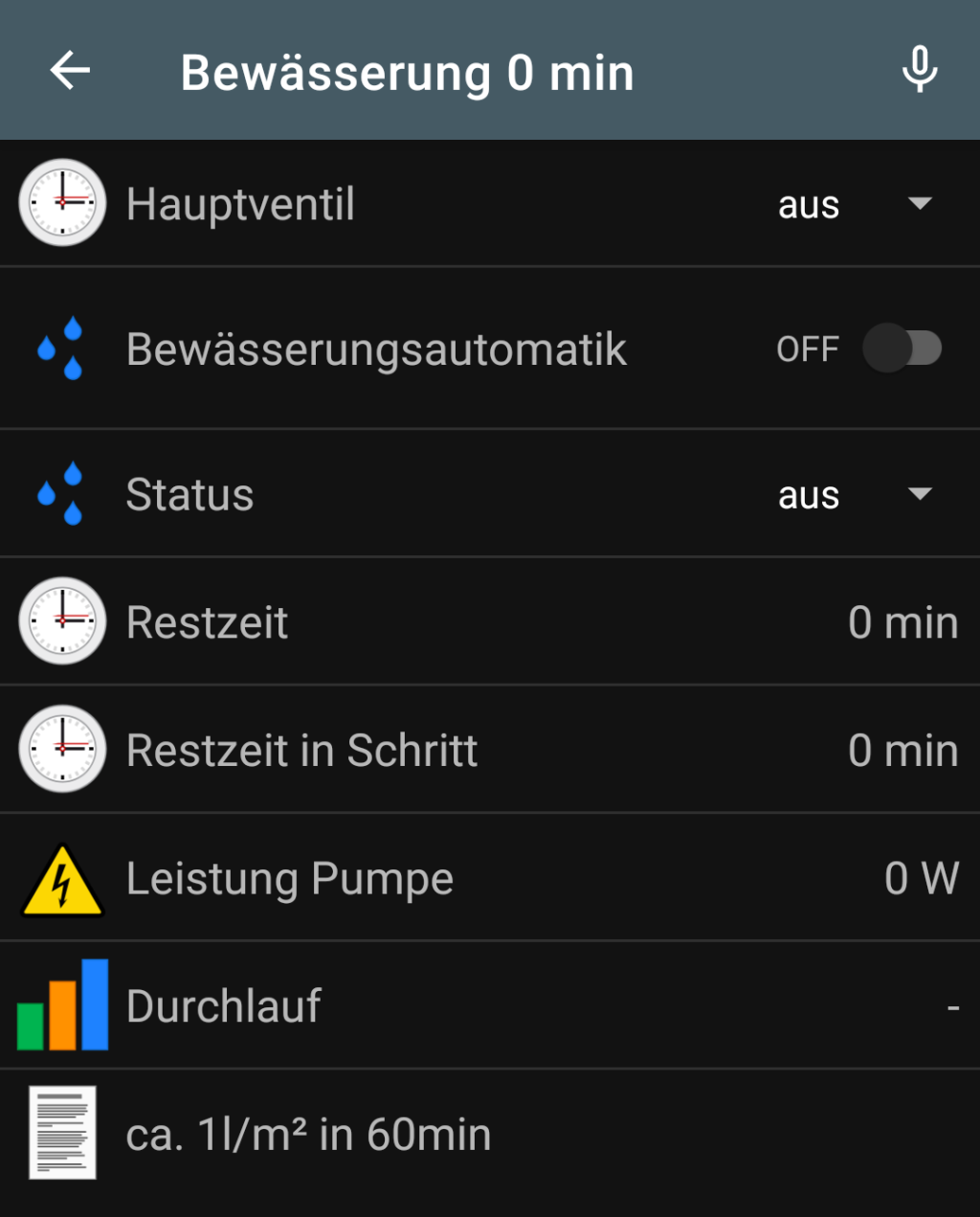
Of course, this MQTT interface is used to integrate the irrigation system into our openHAB app via its MQTT binding, allowing to set a target duration, start the sprinklers, select specific sprinklers and supervise the progress from our phones.
Note that set and update topics are separated to avoid confusion as everything can be set locally at the device as well through buttons and a small display.
So, there is also a small OLED display attached via the Arduino’s I²C bus along with two buttons. These allow controlling the system without an app, which is especially helpful when my parents take care of the house while we are on vacation.
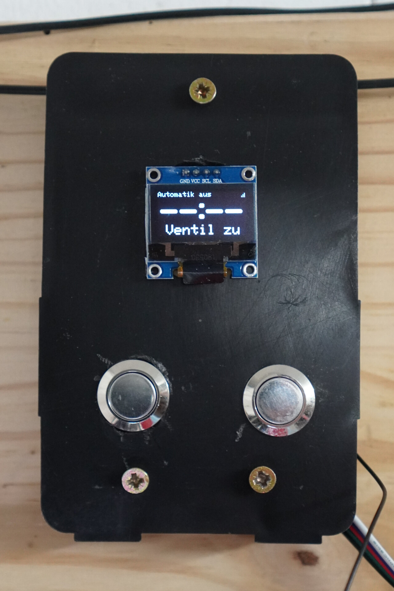
The control is pretty straightforward. The right button increases the duration in 30 minute increments during which the main valve should be open and the left one lowers it until eventually turning the system off. First, this only operates the main valve, but after increasing the duration a few times, it enables automatic irrigation and starts over with a duration of 1 hour.
Surprisingly, the buttons gave me more trouble than expected. It is probably fine to simply check the state of the corresponding inputs, but I went for using interrupts to make them “extra snappy”. However, this introduced the problem that any voltage spike was picked up by the interrupt and could trigger an unintended button press. You can imagine that it was not exactly ideal when turning on the fluorescent light in the garage started the sprinklers because of voltage spikes6. So, if you want to do it in the same way, make sure to add some capacitors parallel to the buttons to “debounce” them.
This system is working for a year now without any trouble whatsoever (except for the fluorescent light incident) and it has survived the winter. By now I even dare to start it remotely before I get home in the evening. With the limited output from the pump and through the thin pipe, this is the only way to water the lawn long enough to get enough water on the entire area. Also, being able to control individual sprinklers is a lot of fun, especially when chasing my son by switching sprinklers on a hot summer day.
This article and the source is not designed to be a step-by-step instruction to build the same system. But if you could follow my explanation and want to set up something similar, please feel free to use my code over at github (released under the GNU GPLv3).
Well, they shoot one strong jet of water across the entire lawn. There are even stronger models, though. ↩
The two T100 and two of the S80s are combined into a group of two. ↩
He learned to do so before he could walk. Now water only comes out of the tap if an adult opens the main valve first. ↩
More does not make sense in my system as the water supply cannot sustain so many sprinklers. ↩
As this term is not heard so often: A nibble is half a byte. So, we have two nibbles of 4 bit each and each nibble can therefore represent numbers from 0 to 15 if you interpret them on their own. In hex notation, this means that 0xf0 sets all four bits of the higher nibble to 1 and the bits of the other nibble to zero. ↩
The starting process of fluorescent tubes can cause these easily. ↩