
02 October 2025
UPDATE A FEW HOURS LATER: Turns out that Natalie the Nerd beat me to it by a few hours. But she did not just beat me in terms of releasing a bit earlier, but also in functionality, style and execution. I fully admit defeat in this undeclared race that every nerd with a public channel just seems to secretly have competed in. I will be forming a “Natalie beat us” support group with all the other just-a-little-too-late-and-not-quite-as-good projects that will be popping up over the next weeks :)
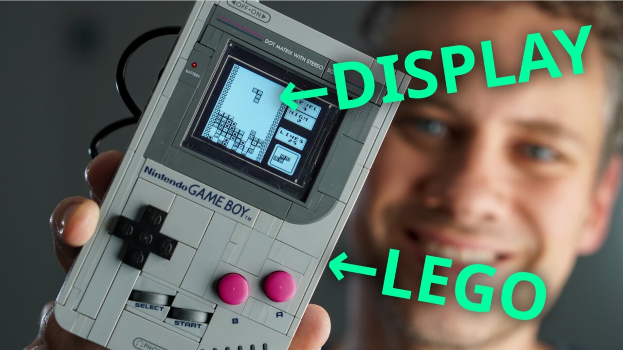
Well, ok, there actually is a Lego Game Boy and it has just been released today yesterday. What there actually oughta be is a real display for it, which this blog post is about.
If you just want to see it in action, check out the Youtube video. If you want to add a display to your own Lego Game Boy, read on for all the details on how to do this.
Please note that this article contains affiliate links, i.e. links that tell the target site that I sent you there and that earn me a share of their revenue in return, i.e. as an Amazon Associate I earn from qualifying purchases. In contrast to regular external links, such affiliate links are marked with a dollar sign instead of a box.
Ok, I probably have to put a short disclaimer in front of this post. No, this is not as fancy and elaborate as many of my other posts. I literally just researched a screen of the right size, looked for a proper open source emulator and put everything together. The biggest contribution from my side might actually be a simple 3D printed adapter. But it worked out so nicely, I just couldn’t resist making a video about it.1
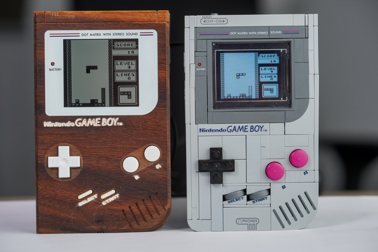
What am I even talking about? Well, about Lego’s new Game Boy model (72046). They released it today, but when I saw its announcement a while ago I knew I had to pre-order it. I also already had a place in mind where I’d put the model on display as it would look really nice next to my Wooden Game Boy. But while I was patiently waiting for its release I realized that there is an important difference between my wooden Game Boy and the Lego Game Boy: The wooden one has a modern IPS backlit display, while the Lego Game Boy does not have an actual display at all.
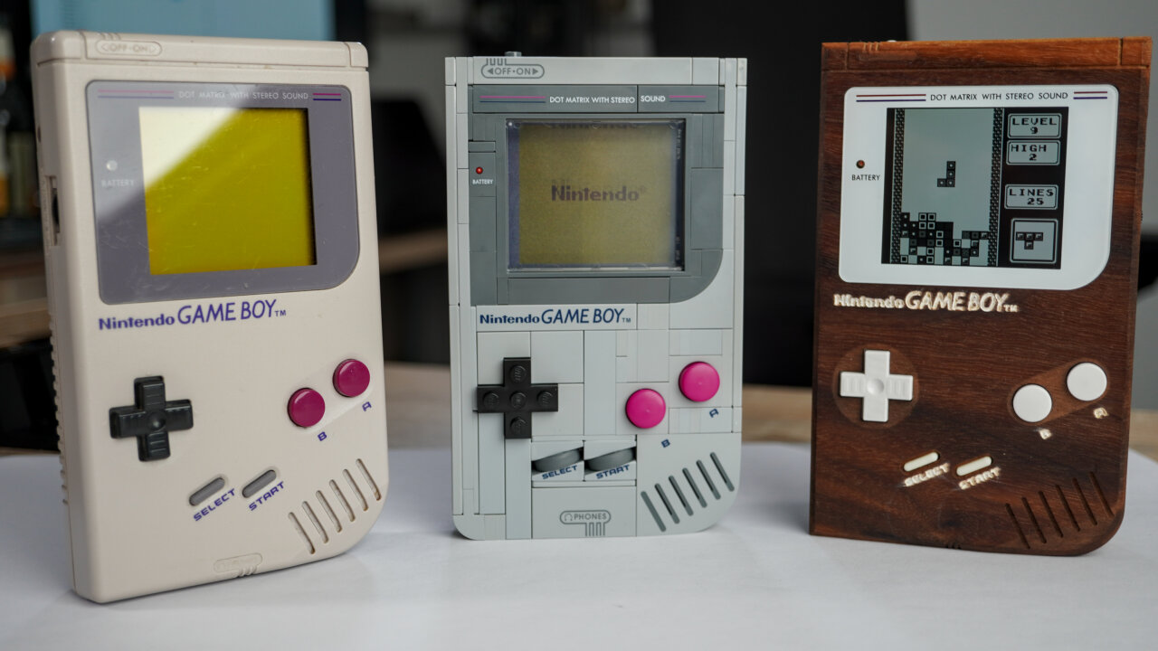
Don’t get me wrong. Lego did not just put a void into the display area of their model. On the contrary: They created linticular displays that look very similar to the original Game Boy and which even simulate a moving image. These are fantastic and such a clever solution!
These lanticular displays are much closer to the original Game Boy than what my wooden Game Boy does and my modification to the Lego model will actually bring it farther away from the original. But the thing is that my wooden Game Boy will literally outshine the Lego one and I want to balance the looks on the shelf by adding a real display.
So, I researched ahead and found that the display of the Lego model is a 6 by 6 window2, which my sons had handily available in their huge Lego stash. With that as a reference I did some research and ended up with a fitting display and a small microcontroller to run it. Here is the parts list, which is really short if you already have common maker tools at hand. In that case, adding a display to your Lego Game Boy can be done for about 25€.
What you need:
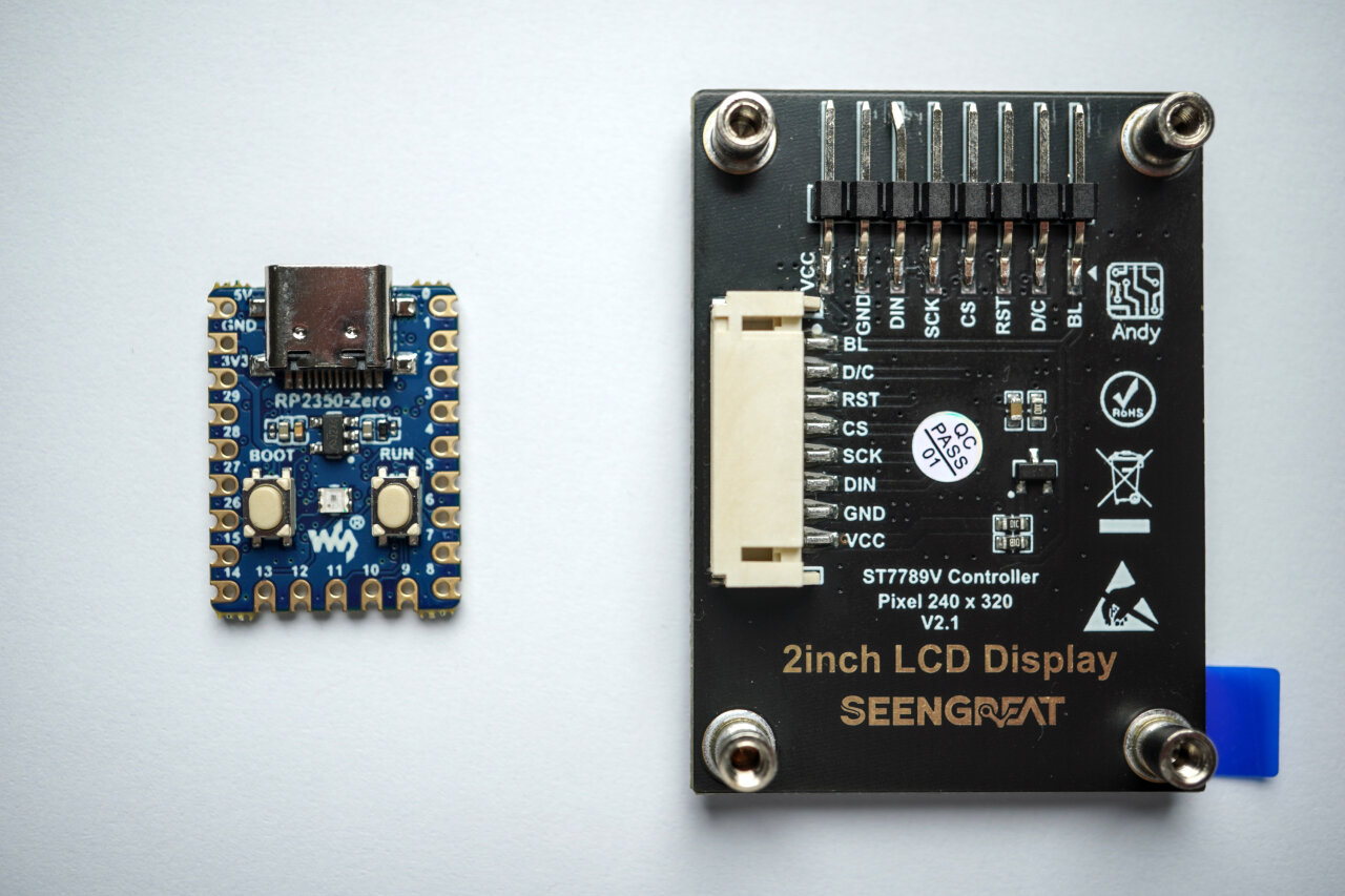
Note, that I am not familiar with Seengreat and I have no idea if you can find the same display under different brand names. The important part is that it is a 320x240 pixels display with an ST7789V SPI controller. Of course the measures also need to be the same (careful when comparing: The distance between the screw threads is wrong in the amazon listing, but that does not matter for this project anyway).
As mentioned in the listing, I am quite sure that you do not need a 3D printer and can just cut some cardboard. If you have little experience with soldering stuff you might want to ask a friend, though, as I do not see a good way around this.
Well, the Lego Game Boy comes with assembly instructions, so let’s assume you already have a fully assembled Lego Game Boy at hand :)
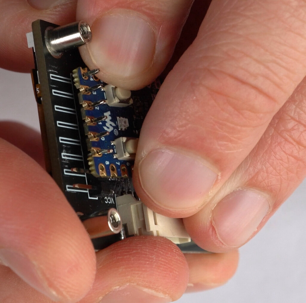
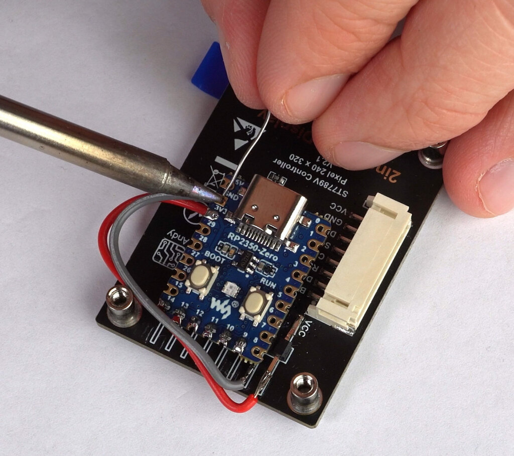
The display has eight pins that you need to connect to our microcontroller. If for some reason you want to connect it differently than I did, you really just need to make sure to connect VCC to the 3V3 pin and GND to GND. All other pins from the display just have to be connected to any GPIO pin on the rp2350. You just need to set up the correct pin mapping in the software later. However, if you want to do exactly what I did, here is the pin mapping I used:
As you can tell from the photos, this mapping allows mostly reusing the pin header that is already soldered onto the display. I directly soldered most of the pins to this header and hooked up the remaining ones with short pieces of wire.
At this point consider to do the software part in the next section first before putting the display into the Game Boy while you can still easily reach the microcontroller. However, it is also not too tricky while it is already in there and I like to keep hardware and software instructions separated, so…
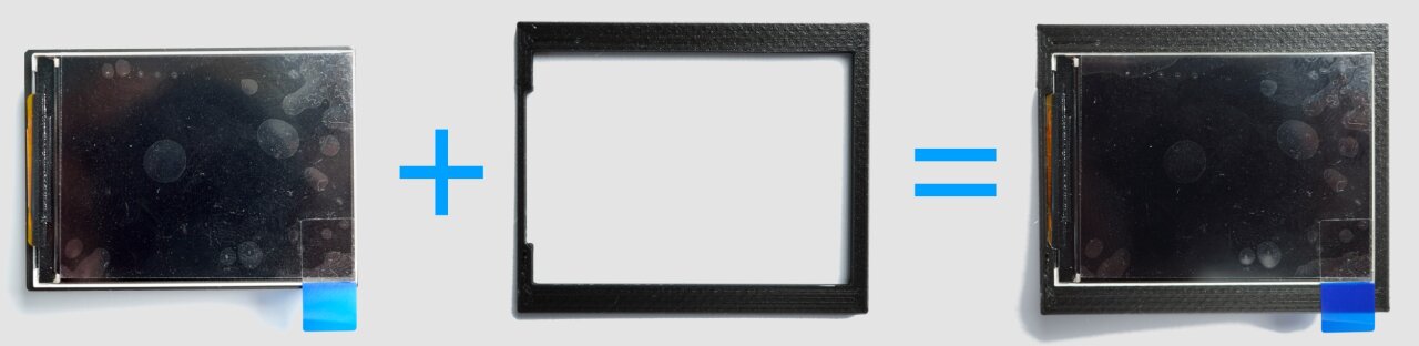
The next thing you need is the simple adapter to hold the display in the center of the Lego window. If you have a 3D printer, simply grab the model from (thingiverse / printables / makerworld - check back in a few minutes) and print it. The display should fit neatly into the center with the flat cable at one side fitting into the gap. Then just put the entire assembly into the Game Boy’s window and you are done. If you do not have a 3D printer, get some thick black cardboard3 and a box cutter to recreate the same shape.
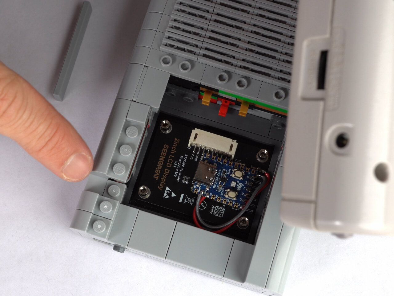
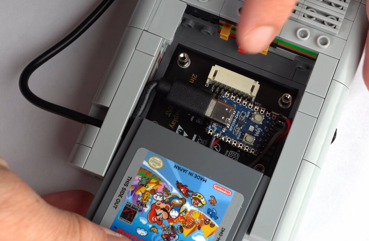
Finally, you just have to attach a USB cable and run it out from your Game Boy. Either do it like I am showing in the photo or remove some bricks if you prefer to run it differently. This may depend on how you want to show the model later and which sides or angles will be visible to the viewer.
Now, here is the good news. This is not just a trick to run some videos on the display. We are going to run an actual emulator with original games on it! The bad news is that, obviously, I cannot just share ROMs of Nintendo’s games here, so you need to obtain a ROM file from your own games first (search the web).
The emulator that we will run on our rp2350 is “Pico-GB”. Originally, this was Peanut-GB by deltabeard, who already ported it as RP2040-GB, which was forked by YouMakeTech as Pico-GB with several improvements and which was then again forked by tobigun with even more improvements, most notably support for many more displays including ours.
Now, before you get confused by all these forks, just get the files from my fork, which has the configuration files already set to match our display and our needs. It also disables sets inputs to GPIO 0 (i.e. out of the way) and selects a grayscale color palette.
Just clone or download the entire repository (if you are unfamiliar with github, you can download a zip with the green button in the top right corner).
In theory, now you already have everything you need, but you have to get your ROM in there, so it will be compiled into the firmware 4. Unfortunately, you cannot just use the binary ROM file that you have, but instead it needs to be converted into a C header file. On Linux you can simply run xxd -i your-ROM.gb > game_bin.h, but on less abled operating systems you can use an online tool. Upload your ROM, press convert and save the file. Then place the file as game_bin.h in the src folder of the repository you just downloaded. Open the file with any text editor and make sure that the first line looks like this:
unsigned char GAME_DATA[] = {
  0x.., 0x.., 0x.., ....
  0x.., 0x.., 0x.., ....
  ...
}
You can ignore or remove any lines starting with // that the conversion tool added. The important part is that the line with GAME_DATA[] = comes directly before the big block of 0x..-entries.
Now it is time to compile and flash the code. This is a PlatformIO project, so you would open VSCode and load the project with PlatformIO. I would give step by step instructions on how to install VSCode and PlatformIO, but I am quite sure that things will be different for non-Linux readers, so please refer to the web if you are stuck as there should be plenty of tutorials for this. You basically only have to install VSCode from Microsoft and then use the Add-On-Store in VSCode to install PlatformIO as a plugin. You then have the alien head or insect head or whatever the icon of PlatformIO is at the left hand side of VSCode and can use that to open the folder that you downloaded from github (not src, but the one containing src). Press the tiny checkmark sign at the bottom to compile, plug in your rp2350 and press the arrow next to the checkmark to upload it to the rp2350. After a moment, your game should show up on the display5.
Well, the result is a display fitting neatly into the Lego Game Boy and running the game you picked. Of course, at this point it does not have sound or any means to control the game, so you should pick a game that runs on its own in some demo mode. You might even want to look for ROM hacks that reduce the wait time for the demo mode or that do something entirely different.
However, if you want to create a fully functional Lego Game Boy, that should be possible, too. The emulator supports inputs via GPIO, it can generate sound and it should be easy to run the rp2350 on a battery. The tricky part will be getting it all into the Lego Game Boy and especially figuring out some kind of contact that works with the Lego Game Boy’s mechanical buttons. I think it can be done, but it would be total overkill for my purpose, so I am eager to hear from you when you managed it :)
And now that I am writing the post, I realize that this might be the first time I have a chance to actually test affiliate links in a meaningful way. But don’t worry, every link has the product name clear enough that you can just search for it yourself if you don’t like those links. ↩
This means that it is a window that is six studs wide and six full-sized lego blocks high. The depth of the window is of course just one stud. ↩
Okay, any cardboard should do if you have a black marker. Just shov it in there and try to make it look nice :) ↩
The emulator’s default solution for this is actually connecting an SD card reader to the rp2350, but since I will not be switching games that often, I did not go that route. If you want that, just look at the emulator’s documentation and change the config files accordingly. ↩
Admittedly, I had some trouble to upload directly from VSCode. If the checkmark worked without any error messages, try the following: In the terminal that eventually printed “pico2 SUCCESS 00:00:05.526” you will see a line like “Building .pio/build/pico2/firmware.bin” (or similar on other operating systems). This is relative to your project folder where you can find the compiled firmware. Look for a file that ends with .uf2. When you found it, plug in your rp2350, then hold its BOOT button, shortly press the RUN button and then release the BOOT button. The rp2350 should now show up as a USB drive on your PC. Throw the uf2 file onto this drive and it should automatically disconnect and reboot with your Game Boy game on it. ↩