
21 July 2025
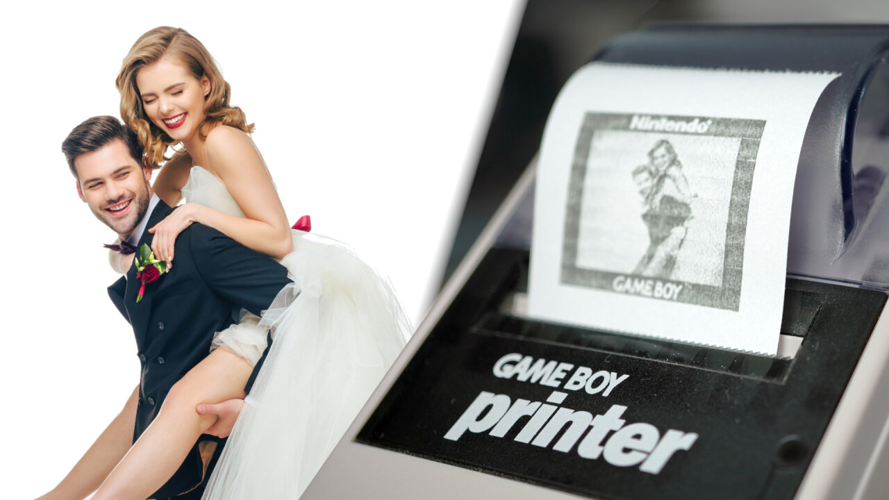
Another one of my cousins got married, so it was time for another photo/video booth. This time it uses a Game Boy Camera and a Game Boy Printer.
The video above gives a good overview of the project. The blog entry below contains a few more technical details as well as links to source code and additional resources.
Please note that this article contains affiliate links, i.e. links that tell the target site that I sent you there and that earn me a share of their revenue in return, i.e. as an Amazon Associate I earn from qualifying purchases. In contrast to regular external links, such affiliate links are marked with a dollar sign instead of a box.
Loyal readers of my blog will certainly remember my bullet time video booth. It was a rig for my cousin’s wedding allowing guests to take short video clips of themselves with a bullet time effect as transition. In fact, building these video booths has become a bit of a tradition as I first created one for my own wedding, followed by a total of three for friends and cousins. Each time resulting in a wonderful memory of the wedding reception with clips from all the guest cut into one long video with upbeat music selected by the couple.
So, when another one of my cousins1 got married, it was time for another one, video booth number five. Since reusing the bullet time rick was not an option due to space constrictions, it was a perfect chance to make a crossover between my camera stuff and my Game Boy stuff to create a Game Boy photo booth. After all, that cousin also loves the old video game systems.
Ok, so what is it? A photo booth or a video booth? Well, both.
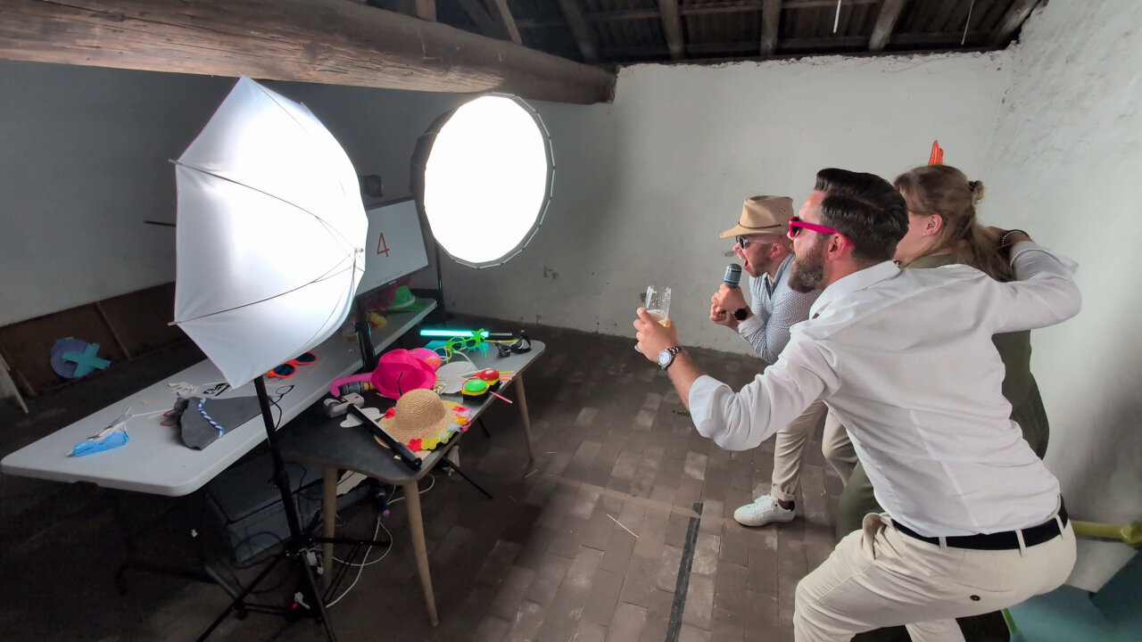
When guests push the green button, they get some intructions and a countdown. At the end of the countdown a five second video clip is recorded using a proper modern mirrorless camera and a Game Boy camera simultaneously, resulting in a bunch of video clips for me to assemble later. That’s a video booth. But with this setup, it does not end here. It also takes three stills from the Game Boy Camera recording and offers the guests to print them through a Game Boy Printer as a souvenir for the guests themselves - like typical photo booths do at many wedding receptions2.
The entire setup does not really do something unusual I haven’t done before, but it combines many different components.
At the heart sits a Raspberry Pi 4, which runs a Python script to control everything and to show a GUI to the guests. That GUI is actually a web-interface, based on Flask and displayed locally via Chromium. In theory, you could use this to show the status of the video booth remotely or display the newest video clips somewhere else at the wedding reception, but I only used it to show the GUI on a screen attached to the same Raspberry Pi for a simple reason: I find it much easier to create a full screen GUI with frame-precise playback3 of multiple videos via HTML5 and JavaScript than doing so with some specialized and OS-specific Python modules4.
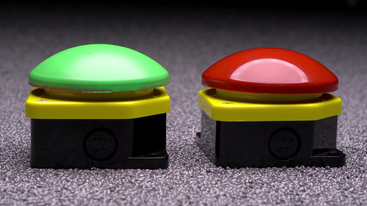
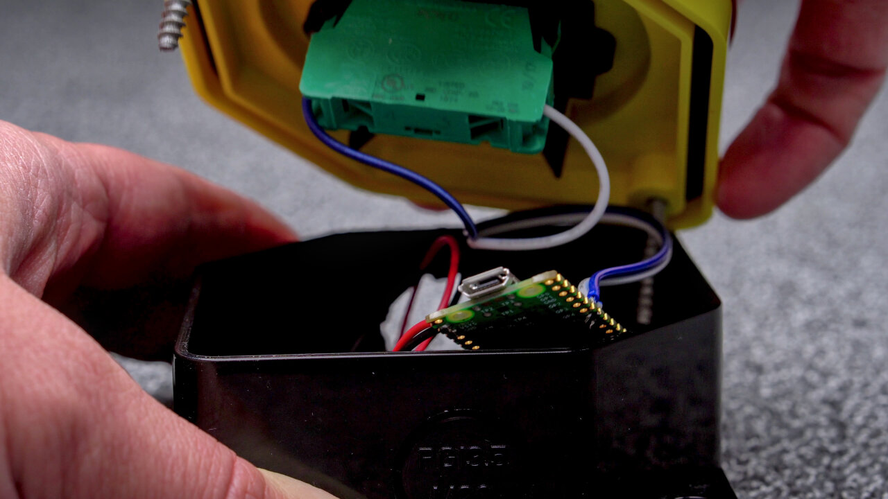
The video box is controlled by two big push buttons. These are exactly the same push buttons I already used for the bullet time video booth. They run on two AA batteries each and have a Raspberry Pi Pico W inside that acts as a Bluetooth Low Energy keyboard, sending only a single button press to the Pi 4 whenever the push button is pressed. Its source code can be found here.
Then there is the main camera, the Game Boy Camera and the Game Boy Printer, which I will discuss in the next sections.
In the context of this project, controlling the main camera, a Sony a6400, should be the boring part, but there are a few details to it that make this trickier than you might think.
In a perfect world, I would just hook up my modern camera to a USB port and be able to control it and to download recorded videos, so I can show the results to the guests. Unfortunately, that’s not possible with the a6400 (no video download in anything but mass storage mode).
In a less perfect, but still somewhat nice world, I would use the camera’s Wifi interface for this, but nope, also not possible on the a6400 (no video download via Wifi).
In a cumbersome but still livable world, I would grab the video directly from the camera through an HDMI grabber, but that is not possible on the a6400 with USB control (one camera stream is reserved for USB preview and hence unavailable for HDMI out).
The combination that actually worked well for me is (brace yourself!) controlling the camera via Bluetooth Low Energy and retrieving the recording through a Wifi SD card. In fact, this is what gave me the idea to create my Bluetooth remote control app for alpha cameras for which I already discussed the different control and retrieval options.
The downside is that I had to limit the resolution to 1080p instead of 4k due to the slow memory card, but compared to the Game Boy Cameras resolution that’s still plenty.

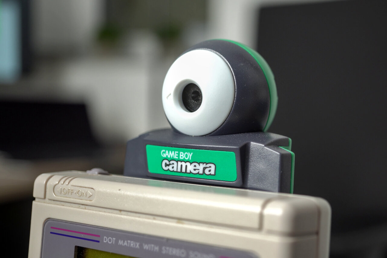
Believe it or not, but recording a video stream from the Game Boy Camera is much simpler. At least if you already have another one of my projects at hand: The GB Interceptor.
Quick explanation if you have not heard of it: It is a little adapter that goes between a Game Boy and a game cartridge (like the Game Boy Camera). It captures the communication between the two to reconstruct what the Game Boy is showing on the screen, all handled by an rp2040 microcontroller. In case of the Game Boy Camera, you can simply enter the shoot mode of the Game Boy Camera and the video will be available to the GB Interceptor.
The GB Interceptor simply acts as a regular USB webcam and since my original article on the GB Interceptor, I managed to implement MJPEG encoding which makes it compatible with pretty much any host device5, including computers and laptops with Linux, Windows and MacOS as well as Android tablets and iPads with iPadOS. If you are interested in learning how encoding MJPEG on an rp2040 works when it is already fully occupied following a Game Boy and rendering its graphics, I would recommend watching my talk at the 37c3 Chaos Communication Congress (yes, I am quite proud of that talk).
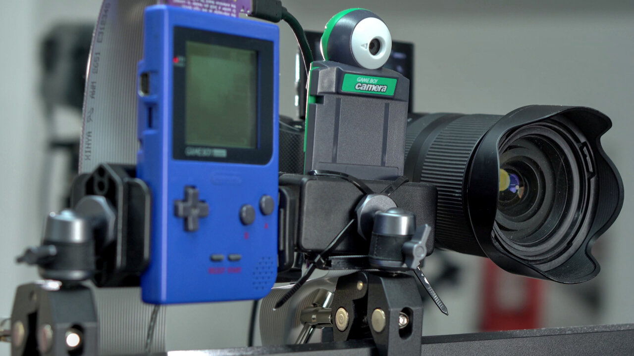
The point is that I only had to use a regular Game Boy, plug in the GB Interceptor, plug in the Game Boy Camera into the GB Interceptor and connect the GB Interceptor with a USB-C cable to the Raspberry Pi. Maybe the only unusual thing is that I used the break-out board of the GB Interceptor PCB to use a long ribbon cable between the Game Boy and the Game Boy Camera, allowing me to position it more freely.


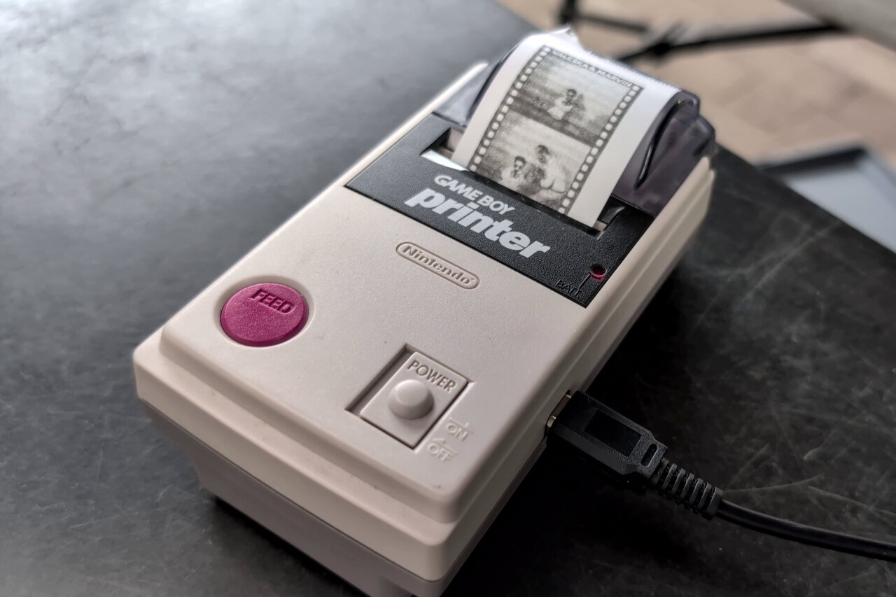
And finally, the Game Boy Printer. This is the part for which I had to write the most code. Not because it was particularly difficult, but simply because I had not done it before.
When I am saying that it was not difficult, then this is the case not because I naturally speak Game Boy Printer, but because I could of course once again count on the Game Boy dev community to have long solved how this is to be done. As always, the gbdev.io Pandocs give all the necessary info in a compact overview, but there are also plenty more explanations for the Game Boy Printer communication to be found on the web.
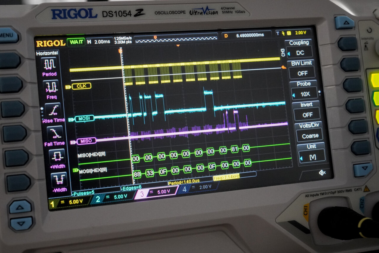
Electrically, the communication is done through a Game Boy link cable, which is basically an SPI interface. In case of the printer it is even more rudimentary as data is never transmitted in both directions at the same time. So, I wrote some minimal Arduino code that receives data through a USB serial interface, writes it as SPI to the Game Boy Printer and returns the answer back to the USB serial.
The Arduino code runs on a 5V variant of the Pro Micro. You know how much I love the Pi Pico / rp2040, but in this case I had to yield to the old technology of the Game Boy Printer, which has a logic level of 5V. So, as the Printer would not accept the 3.3V commands from a Pi Pico, instead of fiddling with level shifters, I simply grabbed the first 5V uC from my collection that I could find - which was a Pro Micro.

The Printer itself is somewhat limited. It can receive commands for line feed and accepts 8 pixel high rows of 2bit tile data in the same format that the Game Boy uses to print batches of eight pixel rows. Its horizontal resolution matches the Game Boy with 160 pixels while you can print endlessly to achieve any vertical resolution. However, it only has internal memory for a single Game Boy sized screen (144 pixels or 18 tile rows), so long images have to be split up into multiple commands. Transfer and printing takes a while although I am driving the Printer’s SPI interface at four times the data rate that could be achieved by the original Game Boy (32kbit/s instead of 8kbit/s).
I wrapped it all into a neat little Python module, which boils it down to a single command that takes an arbitrary image to be printed on the Game Boy Printer. Well, almost arbitrary: The height of the image must be a multiple of eight after it has been scaled to a width of 160 pixels.
You should be able to easily reuse my work by using my Arduino code on almost any 5V micro controller and using my Python module for the Game Boy Printer:
1
2
3
4
from GBPrinter import GBPrinter

with GBPrinter("/dev/ttyACM0", 115200) as gbp:
    gbp.printImageFromFile("testprint.png", 0.5)
The second parameter adjusts the “exposure” of the thermo paper, i.e. making the entire printout darker or brighter.
And a final important tip: You do not have to find some of the rare old stocks of original Game Boy Printer paper or expensive reproductions. Any thermal paper with the right width of 38mm and a not too big roll diameter should do fine.
In the end the guests had a lot of fun and especially my cousin who also appreciates old video games loved the Game Boy video/photo booth. Of course, the final video with the clips from all the guests primarily used the footage from the “good” camera. You would not want this memory of your wedding to be lost in 128x112 pixels6, but I could use the Game Boy Camera footage to spice up the video.
It might also be worth noting that once the setup was running, I did not have to look after it except for refilling the printer paper twice. I emphasize “once it was running”, because I was a bit careless with the quick solder job on the Pro Micro while setting it up, which means that I am now known as that nerd who brought a soldering iron to a wedding. Totally worth it.
Usually, I provide one link to the source for a project, which contains everything, but in this case it is unlikely that you will reuse the entire project (after all, it is quite specific to all the components) and some parts have been reused from previous projects. So, here is an overview of all the bits and pieces already provided throughout the blog article:
This is now cousin 3 of 5, so this might not be the last blog/video on the subject. ↩
Of course, this is what I perceive as “typical”. I could not even say if a wedding tradition is actually typical for Germany or only for the part of Germany where I live. No idea if the rest of the world does the same, but I suspect that a lot of these traditions has been unified by Hollywood. ↩
Frame-precise playback is also the reason that I do most of my presentations in HTML instead of something like PowerPoint. When I started doing this more than ten years ago, the HTML5 players in Chrome and Firefox were pretty much the only ones who could jump to a specific frame and not just the nearest I-frame. Being able to do such jumps and scripting them is so helpful for showing nicely rendered animations. ↩
In fact, I am so used to doing this in HTML, which runs pretty much on any platform, I cannot even be bothered to check which alternatives might be available. ↩
With the Nintendo Switch 2 being a notable exception. Since I do not own a Switch 2 I cannot test this, but I suspect that it rejects the odd resolution with a 10:9 aspect ratio. ↩
Yes, the Game Boy Camera resolution is even lower than the Game Boy’s 160x144. ↩